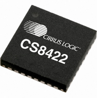
CS8422-CNZ Cirrus Logic Inc, CS8422-CNZ Datasheet - Page 29

CS8422-CNZ
Manufacturer Part Number
CS8422-CNZ
Description
IC SAMPLE RATE CONVERTER 32QFN
Manufacturer
Cirrus Logic Inc
Type
Sample Rate Converterr
Datasheet
1.CS8422-CNZ.pdf
(82 pages)
Specifications of CS8422-CNZ
Package / Case
32-QFN
Applications
Digital Audio
Mounting Type
Surface Mount
Maximum Operating Temperature
+ 125 C
Minimum Operating Temperature
- 55 C
Mounting Style
SMD/SMT
Package
32QFN
Operating Temperature
-55 to 125 °C
Audio Control Type
Sample Rate Converter
Control Interface
I2C, SPI
Supply Voltage Range
1.71V To 5.25V
Operating Temperature Range
-40°C To +85°C
Audio Ic Case Style
QFN
No. Of Pins
32
Rohs Compliant
Yes
Lead Free Status / RoHS Status
Lead free / RoHS Compliant
For Use With
598-1568 - BOARD EVAL FOR CS8422 RCVR
Lead Free Status / Rohs Status
Lead free / RoHS Compliant
Other names
598-1732
Available stocks
Company
Part Number
Manufacturer
Quantity
Price
Company:
Part Number:
CS8422-CNZ
Manufacturer:
CIRRUS
Quantity:
99
Part Number:
CS8422-CNZ
Manufacturer:
CIRRUS
Quantity:
20 000
Part Number:
CS8422-CNZR
Manufacturer:
CIRRUS
Quantity:
20 000
DS692F1
6. DIGITAL INTERFACE RECEIVER
The CS8422 includes a digital interface receiver that can receive and decode audio data according to the AES3,
IEC60958, S/PDIF, and EIJ CP1201 interface standards.
The CS8422 uses either a 4:1 single-ended or 2:1 differential input mux to select the input pin(s) that will receive
input data to be decoded. A low-jitter clock (RMCK) is recovered using a PLL, which provides the digital interface
receiver with a master clock. The decoded audio data can either be routed through the SRC for sample rate con-
version, or can be an output on one of two serial audio output ports. The channel status and Q-subcode data portion
of the user data are assembled and buffered in
-
6.1
6.2
6.2.1
6.2.2
22h), and may be accessed through the control port in either SPI or I²C Mode.
AES3 and S/PDIF Standards
This document assumes that the user is familiar with the AES3 and S/PDIF data formats. It is advisable to
have current copies of the AES3, IEC60958, IEC61937, and EIJ CP1201 specifications on hand for easy
reference.
The latest AES3 standard is available from the Audio Engineering Society at www.aes.org. The latest
IEC60958/61937 standard is available from the International Electrotechnical Commission at www.iec.ch.
The latest EIAJ CP-1201 standard is available from the Japanese Electronics Bureau at
ta.or.jp/eiaj/.
Application Note 22: Overview of Digital Audio Interface Data Structures, available at www.cirrus.com, con-
tains a useful tutorial on digital audio specifications, but it should not be considered a substitute for the stan-
dards.
The paper titled An Understanding and Implementation of the SCMS Serial Copy Management System for
Digital Audio Transmission, by Clifton Sanchez, is an excellent tutorial on SCMS. It is available from the
AES as reprint 3518.
Receiver Input Multiplexer
The CS8422’s receiver input multiplexer allows input of data compatible with AES3, S/PDIF, IEC60958, and
EIAJ CP-1201 standards. For information about recommended receiver input circuits, see
er Components” on page
Hardware Mode Control
In Hardware Mode, the receiver input multiplexer is limited to a selection between two differential inputs,
RXP0/RXN0 and RXP1/RXN1. The receiver input multiplexer will decode data present at the differential
input selected by the RX_SEL pin. See
Multiplexer inputs are floating when not selected. Unused inputs should be tied to AGND/DGND
Software Mode Control
In Software Mode, CS8422 offers either a 4:1 single-ended, or a 2:1 differential input multiplexer to ac-
commodate switching between up to four channels of AES3 or S/PDIF-compatible data input. In Single-
Ended Mode, the CS8422 can switch between four single-ended signals present at RX[3:0]. In differential
mode, the CS8422 can switch between two differential signals, present on RXP0/RXN0 and RXP1/RXN1.
Multiplexer inputs are floating when not selected. Unused inputs should be tied to AGND/DGND
In Software Mode, the receiver input multiplexer is controlled through the register described in
11.3 “Receiver Input Control (03h)” on page
64.
Channel Status Registers (23h - 2Ch)
Section 8. “Hardware Mode Control” on page 39
48.
and
Q-Channel Subcode (19h
“External Receiv-
for more details.
CS8422
www.jei-
Section
29


