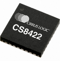
CS8422-CNZ Cirrus Logic Inc, CS8422-CNZ Datasheet - Page 57

CS8422-CNZ
Manufacturer Part Number
CS8422-CNZ
Description
IC SAMPLE RATE CONVERTER 32QFN
Manufacturer
Cirrus Logic Inc
Type
Sample Rate Converterr
Datasheet
1.CS8422-CNZ.pdf
(82 pages)
Specifications of CS8422-CNZ
Package / Case
32-QFN
Applications
Digital Audio
Mounting Type
Surface Mount
Maximum Operating Temperature
+ 125 C
Minimum Operating Temperature
- 55 C
Mounting Style
SMD/SMT
Package
32QFN
Operating Temperature
-55 to 125 °C
Audio Control Type
Sample Rate Converter
Control Interface
I2C, SPI
Supply Voltage Range
1.71V To 5.25V
Operating Temperature Range
-40°C To +85°C
Audio Ic Case Style
QFN
No. Of Pins
32
Rohs Compliant
Yes
Lead Free Status / RoHS Status
Lead free / RoHS Compliant
For Use With
598-1568 - BOARD EVAL FOR CS8422 RCVR
Lead Free Status / Rohs Status
Lead free / RoHS Compliant
Other names
598-1732
Available stocks
Company
Part Number
Manufacturer
Quantity
Price
Company:
Part Number:
CS8422-CNZ
Manufacturer:
CIRRUS
Quantity:
99
Part Number:
CS8422-CNZ
Manufacturer:
CIRRUS
Quantity:
20 000
Part Number:
CS8422-CNZR
Manufacturer:
CIRRUS
Quantity:
20 000
DS692F1
11.16 Interrupt Mode (10h)
11.17 Receiver Channel Status (11h)
Reserved
AUX3
7
7
to 0, the error is masked, meaning that its occurrence will not affect the internal INT signal or the status reg-
ister. The bit positions align with the corresponding bits in Interrupt Status register. This register defaults to
00h.
The INT signal may be selected to output on the GPO pins. See
The interrupt mode control in the behavior of the INT pin to RERR and SRC_UNLOCK interrupts. There are
three ways to set the INT pin active in accordance with the interrupt condition. In the Rising edge active
mode, the INT pin becomes active on the arrival of the interrupt condition. In the Falling edge active mode,
the INT pin becomes active on the removal of the interrupt condition. In Level active mode, the INT interrupt
pin becomes active during the interrupt condition. Be aware that the active level (Active High or Low) only
depends on the INT[1:0] bits. These registers default to 00h. The interrupts in the Interrupt Status register
not represented here are all rising edge active.
The bits in this register can be associated with either channel A or B of the received data. The desired chan-
nel is selected with the CHS bit of
AUX3:0 - Incoming auxiliary data field width, as indicated by the incoming channel status bits, decoded ac-
cording to IEC60958 and AES3.
PRO - Channel status block format indicator
00 - Rising edge active
01 - Falling edge active
10 - Level active
11 - Reserved
0000 - Auxiliary data is not present.
0001 - Auxiliary data is 1 bit long.
0010 - Auxiliary data is 2 bits long.
0011 - Auxiliary data is 3 bits long.
0100 - Auxiliary data is 4 bits long.
0101 - Auxiliary data is 5 bits long.
0110 - Auxiliary data is 6 bits long.
0111 - Auxiliary data is 7 bits long.
1000 - Auxiliary data is 8 bits long.
1001 - 1111 Reserved
0 - Received channel status block is in the consumer format.
Reserved
AUX2
6
6
Reserved
5
AUX1
5
“Receiver Data Control (04h)” on page
Reserved
4
AUX0
4
RERR1
3
0
PRO
3
RERR0
Section 11.5 on page 50
2
0
COPY
2
SRC_UNLOCK1 SRC_UNLOCK0
48.
1
0
ORIG
1
for more details.
CS8422
EMPH
0
0
0
57


