1934350-1 TE Connectivity, 1934350-1 Datasheet - Page 2
1934350-1
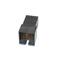
Manufacturer Part Number
1934350-1
Description
Manufacturer
TE Connectivity
Datasheet
1.1934219-1.pdf
(8 pages)
Specifications of 1934350-1
Connector Type
Header
Pcb Mounting Orientation
Right Angle
Pcb Mount Retention
With
Termination Method To Pc Board
Through Hole - Press Fit
Pcb Mount Alignment
Without
Sealed
No
Ul File Number
E28476
Stackable
No
Data Rate (gb/s)
10.000
Differential Impedance (?)
100
Contact - Rated Current (a)
0.5
Hot Pluggable
No
Operating Voltage Reference
AC
Operating Voltage (vac)
250
Tail Length (mm [in])
2.2 [0.087]
Header Type
Fully Shrouded
Number Of Positions
120
Number Of Signal Positions
80
Number Of Rows
15
Number Of Columns
8
Pcb Mount Retention Type
Compliant Posts
Centerline (mm [in])
1.91 [0.075]
Row-to-row Spacing (mm [in])
1.40 [0.055]
Mating Retention
Without
Contact Type
Pin
Contact Design
Rectangular Post
Contact Base Material
Phosphor Bronze
Contact Plating, Mating Area, Material
Gold
Contact Plating, Mating Area, Thickness (µm [?in])
0.76 [29.92]
Tail Plating Material
Matte Tin
Tail Plating, Thickness (µm [?in])
0.5 [20]
Connector Style
Plug
End Wall Location
Dual
Housing Color
Black
Mating Alignment
With
Mating Alignment Type
Guide Slot
Housing Material
Liquid Crystal Polymer (LCP)
Ul Flammability Rating
UL 94V-0
Number Of Pairs Per Connector
40
Pairs Per Column
5
Differential Signaling
With
Rohs/elv Compliance
RoHS compliant, ELV compliant
Lead Free Solder Processes
Not relevant for lead free process
Rohs/elv Compliance History
Always was RoHS compliant
Agency/standard
UL
Ul Rating
Recognized
Ul Voltage Rating (vac)
250
Operating Temperature (°c [°f])
-65 – +90 [-85 – +194]
Board-to-board Configuration
Co-Planar
Pcb Thickness, Recommended (mm [in])
1.57 [0.062]
Contact Transmits (typical Application)
Signal (Data)
Packaging Method
Tube


3.3.
3.4.
3.5.
Initial exam ination of product.
Final examination of product.
Low level contact resistance.
Low level com pliant pin resistance.
Insulation resistance.
W ithstanding voltage.
Tem perature rise vs current.
Rev B
Ratings
!
!
!
Perform ance and Test Description
Product is designed to m eet the electrical, m echanical and environm ental perform ance requirem ents
specified in Figure 1. Unless otherwise specified, all tests shall be perform ed at am bient environm ental
conditions.
Test Requirem ents and Procedures Sum m ary
Test Description
Voltage: 250 volts AC m axim um peak (a of m inim um breakdown voltage)
Current: 0.5 ampere per signal contact (fully loaded)
Tem perature: -65 to 90°C
Meets requirem ents of product
drawing.
Meets visual requirem ents.
100 m illiohm s m axim um initial.
∆R 10 m illiohm s m axim um
individual reading final (applies to
both signal and ground contacts).
1 m illiohm m axim um initial.
∆R 1 m illiohm m axim um change
from initial.
1000 m egohm s m inim um .
One m inute hold with no breakdown
or flashover.
30°C m axim um tem perature rise at
.5 am pere per signal contact, fully
energized.
Figure 1 (continued)
ELECTRICAL
Requirem ent
EIA-364-18.
Visual and dim ensional (C of C)
inspection per product drawing.
EIA-364-18.
Visual inspection.
EIA-364-23.
Subject specim ens to 100
m illiam peres m axim um and 20
m illivolts m axim um open circuit
voltage.
See Figure 3.
EIA-364-23.
Subject specim ens to 100
m illiam peres m axim um and 20
m illivolts m axim um open circuit
voltage. Measurem ents shall be
taken between PCB hole and pin
tip.
EIA-364-21.
100 volts DC, 2 m inute hold.
Test between adjacent contacts of
m ated specim ens.
EIA-364-20, Condition I.
560 volts AC at sea level.
Test between adjacent contacts of
m ated specim ens.
EIA-364-70, Method 1.
Stabilize at a single current level
until 3 readings at 5 m inute intervals
are within 1°C.
Procedure
108-2303
2 of 8
Related parts for 1934350-1
Image
Part Number
Description
Manufacturer
Datasheet
Request
R

Part Number:
Description:
Printers THERMAL PRINTER HS-SLEEVE MARKER
Manufacturer:
TE Connectivity


Part Number:
Description:
Manufacturer:
TE Connectivity
Datasheet:


Part Number:
Description:
Manufacturer:
TE Connectivity
Datasheet:

Part Number:
Description:
Manufacturer:
TE Connectivity
Datasheet: