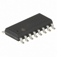
ISL59444IBZ-T13 Intersil, ISL59444IBZ-T13 Datasheet - Page 7

ISL59444IBZ-T13
Manufacturer Part Number
ISL59444IBZ-T13
Description
IC AMP MULTIPLEX 1GHZ 16SOIC
Manufacturer
Intersil
Datasheet
1.ISL59444IBZ.pdf
(11 pages)
Specifications of ISL59444IBZ-T13
Applications
4:1 Multiplexer-Amplifier
Number Of Circuits
1
-3db Bandwidth
1GHz
Slew Rate
1515 V/µs
Current - Supply
18mA
Current - Output / Channel
180mA
Voltage - Supply, Single/dual (±)
±4.5 V ~ 5.5 V
Mounting Type
Surface Mount
Package / Case
16-SOIC (0.154", 3.90mm Width)
Lead Free Status / RoHS Status
Lead free / RoHS Compliant
Typical Performance Curves
Pin Descriptions
PIN NUMBER
FIGURE 19. PACKAGE POWER DISSIPATION vs AMBIENT
2, 6, 8
10
11
12
13
14
15
16
1
3
4
5
7
9
1.4
1.2
0.8
0.6
0.4
0.2
1
0
0
JEDEC JESD51-7 HIGH EFFECTIVE THERMAL
CONDUCTIVITY TEST BOARD
1.250W
TEMPERATURE
25
PIN NAME
AMBIENT TEMPERATURE (°C)
GND
OUT
NIC
LE1
LE2
IN0
IN1
IN2
IN3
HIZ
V -
S1
S0
V+
50
7
75
85
EQUIVALENT
CIRCUIT
100
Circuit 3
Circuit 1
Circuit 1
Circuit 4
Circuit 1
Circuit 1
Circuit 4
Circuit 2
Circuit 2
Circuit 2
Circuit 2
Circuit 2
Circuit 4
V
S
=
125
±
5V, R
Input for channel 0
Not Internally Connected; it is recommended this pin be tied to ground to minimize
crosstalk.
Input for channel 1
Ground pin
Input for channel 2
Input for channel 3
Negative Power Supply
Synchronized channel switching: When LE1 is low, the master control latch loads the
next switching address. The Mux Amp is configured for this address when LE2 goes low.
Synchronized operation results when LE2 is the inverse of LE1. Channel selection is
asynchronous (changes with any control signal change) if both LE1 and LE2 are both
low.
Synchronized channel switching: When LE2 is low, the newly selected channel, stored
in the master latch via LE1 is selected. Synchronized operation results when LE2 is the
inverse of LE1. Channel selection is asynchronous (changes with any control signal
change) if both LE1 and LE2 are both low.
Output
Output disable (active high); there are internal pull-down resistors, so the device will be
active with no connection; "HI" puts the output in high impedance state.
Channel selection pin MSB (binary logic code)
Channel selection pin LSB (binary logic code)
Positive power supply
150
L
= 500Ω to GND, T
ISL59444
A
FIGURE 20. PACKAGE POWER DISSIPATION vs AMBIENT
= 25°C, unless otherwise specified. (Continued)
0.9
0.8
0.7
0.6
0.5
0.4
0.3
0.2
0.1
1
0
0
JEDEC JESD51-3 LOW EFFECTIVE THERMAL
CONDUCTIVITY TEST BOARD
909mW
TEMPERATURE
DESCRIPTION
25
AMBIENT TEMPERATURE (°C)
50
75
85
100
125
September 21, 2005
150
FN7451.1


