ISL59117IIZ-T7 Intersil, ISL59117IIZ-T7 Datasheet - Page 9
ISL59117IIZ-T7
Manufacturer Part Number
ISL59117IIZ-T7
Description
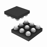
IC VIDEO DRVR TRI-CHN LPF WLCSP
Manufacturer
Intersil
Datasheet
1.ISL59117IIZ-T7.pdf
(10 pages)
Specifications of ISL59117IIZ-T7
Applications
Reconstruction Filter
Output Type
Rail-to-Rail
Number Of Circuits
3
-3db Bandwidth
9MHz
Slew Rate
40 V/µs
Current - Supply
3.9mA
Current - Output / Channel
145mA
Voltage - Supply, Single/dual (±)
2.5 V ~ 3.6 V
Mounting Type
Surface Mount
Package / Case
9-WLCSP
Lead Free Status / RoHS Status
Lead free / RoHS Compliant


Power Dissipation
With the high output drive capability of the ISL59117, it is
possible to exceed the +125°C absolute maximum junction
temperature under certain load current conditions.
Therefore, it is important to calculate the maximum junction
temperature for an application to determine if load conditions
or package types need to be modified to assure operation of
the amplifier in a safe operating area.
The maximum power dissipation allowed in a package is
determined according to:
PD
Where:
The maximum power dissipation actually produced by an IC
is the total quiescent supply current times the total power
supply voltage, plus the power in the IC due to the load, or:
for sourcing:
for sinking:
Where:
PD
PD
T
T
Θ
V
I
V
R
I
SMAX
LOAD
MAX
AMAX
JMAX
MAX
MAX
S
OUT
JA
LOAD
= Supply voltage
= Thermal resistance of the package
=
= Maximum output voltage of the application
=
=
= Load current
= Maximum quiescent supply current
= Maximum junction temperature
= Maximum ambient temperature
= Load resistance tied to ground
T
-------------------------------------------- -
V
V
JMAX
S
S
×
×
I
I
Θ
SMAX
SMAX
–
JA
T
AMAX
+
+
(
(
V
V
S
OUT
–
V
9
–
OUT
V
S
)
)
×
×
V
--------------- -
I
LOAD
OUT
R
L
ISL59117
Power Supply Bypassing Printed Circuit Board
Layout
As with any modern operational amplifier, a good printed
circuit board layout is necessary for optimum performance.
Lead lengths should be as short as possible. The power
supply pin must be well bypassed to reduce the risk of
oscillation. For normal single supply operation, a single
4.7µF tantalum capacitor in parallel with a 0.1µF ceramic
capacitor from V
Printed Circuit Board Layout
For good AC performance, parasitic capacitance should be
kept to minimum. Use of wire wound resistors should be
avoided because of their additional series inductance. Use
of sockets should also be avoided if possible. Sockets add
parasitic inductance and capacitance that can result in
compromised performance.
S
+ to GND will suffice.
September 21, 2006
FN6278.0
Related parts for ISL59117IIZ-T7
Image
Part Number
Description
Manufacturer
Datasheet
Request
R

Part Number:
Description:
Triple Channel Video Driver With Lpf
Manufacturer:
Intersil Corporation
Datasheet:
Part Number:
Description:
Intersil Corporation [CMOS Serial Controller Interface]
Manufacturer:
Intersil Corporation
Datasheet:
Part Number:
Description:
Manufacturer:
Intersil Corporation
Datasheet:
Part Number:
Description:
357-036-542-201 CARDEDGE 36POS DL .156 BLK LOPRO
Manufacturer:
Intersil Corporation
Datasheet:
Part Number:
Description:
1024-Word x 4-Bit LSI Static RAM
Manufacturer:
Intersil Corporation
Datasheet:
Part Number:
Description:
General Purpose NPN Transistor Arrays FN341.4
Manufacturer:
Intersil Corporation
Datasheet:
Part Number:
Description:
CMOS 16-Bit Microprocessor
Manufacturer:
Intersil Corporation
Datasheet:
Part Number:
Description:
Manufacturer:
Intersil Corporation
Datasheet:
Part Number:
Description:
Manufacturer:
Intersil Corporation
Datasheet:
Part Number:
Description:
Manufacturer:
Intersil Corporation
Datasheet:
Part Number:
Description:
Manufacturer:
Intersil Corporation
Datasheet:
Part Number:
Description:
CMOS 6-Bit Latch and Decoder Memory Interfaces
Manufacturer:
Intersil Corporation
Datasheet:
Part Number:
Description:
CA3046General Purpose NPN Transistor Arrays
Manufacturer:
Intersil Corporation
Datasheet:
Part Number:
Description:
Manufacturer:
Intersil Corporation
Datasheet:
Part Number:
Description:
TR909 DLC/FLC SLIC with Low Power Standby
Manufacturer:
Intersil Corporation
Datasheet: