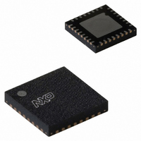
NE58633BS,157 NXP Semiconductors, NE58633BS,157 Datasheet - Page 15

NE58633BS,157
Manufacturer Part Number
NE58633BS,157
Description
IC AMP AUDIO .04W STER D 32HVQFN
Manufacturer
NXP Semiconductors
Type
Class Dr
Datasheet
1.NE58633BS157.pdf
(27 pages)
Specifications of NE58633BS,157
Output Type
Headphones, 2-Channel (Stereo)
Package / Case
32-VQFN Exposed Pad, 32-HVQFN, 32-SQFN, 32-DHVQFN
Max Output Power X Channels @ Load
40mW x 2 @ 16 Ohm
Voltage - Supply
0.9 V ~ 1.7 V
Features
Depop, Differential Inputs, Microphone, Mute, Short-Circuit Protection
Mounting Type
Surface Mount
Product
Class-D
Output Power
40 mW
Available Set Gain
100 dB
Thd Plus Noise
1 %
Supply Current
5 mA
Maximum Operating Temperature
+ 70 C
Mounting Style
SMD/SMT
Audio Load Resistance
32 Ohms
Input Offset Voltage
1 mV
Input Signal Type
Single
Minimum Operating Temperature
0 C
Output Signal Type
Differential, Single
Supply Type
Single
Supply Voltage (max)
1.7 V
Supply Voltage (min)
0.9 V
Lead Free Status / RoHS Status
Lead free / RoHS Compliant
Other names
935283227157
NE58633BS
NE58633BS
NE58633BS
NE58633BS
NXP Semiconductors
NE58633_3
Product data sheet
Fig 15. Switching waveform at the BS pin
(1) Positive or negative output of the class-D driver with V
(2) Pin BS (V
(3) Current at pin B_IN (I
Remark: This is a normal pulse. It does not change with V
specification.
10.4.1 Boost converter operation
10.2 Power supply decoupling
10.3 Speaker output filtering considerations
10.4 Boost converter and layout considerations
BS
= V
bst
The power supply pins B_IN, PVDDL and PVDDR are decoupled with 1 μF capacitors
directly from the pins to ground.
The ferrite beads form a low-pass filter with a shunt capacitor to reduce radio
frequency > 1 MHz. Choose a ferrite bead with high-impedance at high frequencies and
low-impedance at low frequencies. A typical ferrite bead is 600 Ω at 100 MHz. A shunt
capacitor is added after the ferrite bead to complete the low-pass filter. The low frequency
impedance is not as important as in power amplifiers because headphone speakers are
stabilized with a series impedance of about 18 Ω on each output. The series resistors, R
may be decreased to increase the power delivered to the speaker load.
Figure 8
The boost converter operates in asynchronous mode as shown in
drops, the boost converter efficiency decreases (see
converter is capable of driving 2.65 mA external load (see
If the NE58633 is operated without the boost converter, pins B_IN, PVDDL and PVDDR
may be powered directly from a 3 V power supply source such as 2 AAA alkaline
batteries. The VBAT pin is not used.
).
(1)
(2)
(3)
bst(load)O
show the THD+N versus P
) measures approximately 40 mA peak, but averaged DC current is a few milliamperes per the
Rev. 03 — 19 January 2010
BAT
2 Gs/s
at 1.5 V.
BAT
Noise reduction class-D headphone driver amplifier
o
but remains at the level of the boosted voltage.
performance for R
Figure 3
s
= 0 Ω and R
Figure
and
5).
Figure
Figure
s
002aad957
NE58633
= 18 Ω.
© NXP B.V. 2010. All rights reserved.
Figure 7
15. As V
6). The boost
and
BAT
15 of 27
s
,


