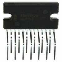
TDA1552Q/N4,112 NXP Semiconductors, TDA1552Q/N4,112 Datasheet - Page 7

TDA1552Q/N4,112
Manufacturer Part Number
TDA1552Q/N4,112
Description
IC AMP AUDIO PWR 22W QUAD 13SIL
Manufacturer
NXP Semiconductors
Type
Class Br
Datasheet
1.TDA1552QN4112.pdf
(10 pages)
Specifications of TDA1552Q/N4,112
Package / Case
13-SIL (Bent and Staggered Leads)
Output Type
4-Channel (Quad)
Max Output Power X Channels @ Load
22W x 2 @ 4 Ohm
Voltage - Supply
6 V ~ 18 V
Features
Depop, Mute, Short-Circuit and Thermal Protection, Standby
Mounting Type
Through Hole
Operating Supply Voltage
18 V
Supply Current
80 mA
Maximum Operating Temperature
150 C
Mounting Style
SMD/SMT
Minimum Operating Temperature
- 55 C
Operational Class
Class-B
Audio Amplifier Output Configuration
2-Channel Stereo
Output Power (typ)
22x2W
Audio Amplifier Function
Speaker
Total Harmonic Distortion
0.1%
Single Supply Voltage (typ)
14.4V
Dual Supply Voltage (typ)
Not RequiredV
Power Supply Requirement
Single
Power Dissipation
60W
Rail/rail I/o Type
No
Single Supply Voltage (min)
6V
Single Supply Voltage (max)
18V
Dual Supply Voltage (min)
Not RequiredV
Dual Supply Voltage (max)
Not RequiredV
Mounting
Through Hole
Pin Count
13
Package Type
DBS13P
Lead Free Status / RoHS Status
Lead free / RoHS Compliant
Lead Free Status / RoHS Status
Lead free / RoHS Compliant, Lead free / RoHS Compliant
Other names
568-3506-5
935054880112
TDA1552QU
935054880112
TDA1552QU
Philips Semiconductors
AC CHARACTERISTICS
V
Notes to the characteristics
1. The circuit is DC adjusted at V
2. At 18 V < V
3. Conditions:
4. Frequency response externally fixed.
5. Ripple rejection measured at the output with a source impedance of 0
6. Frequency f = 100 Hz.
7. Frequency between 1 kHz and 10 kHz.
8. Noise voltage measured in a bandwidth of 20 Hz to 20 kHz.
9. Noise output voltage independent of R
July 1994
Output power
Output power at V
Total harmonic distortion
Power bandwidth
Low frequency roll-off
High frequency roll-off
Closed loop voltage gain
Supply voltage ripple rejection
Input impedance
Noise output voltage
Channel separation
Channel unbalance
P
2 x 22 W BTL stereo car radio power
amplifier
= 14.4 V; R
a) V
b) short-circuit to GND
c) switch V
ON
mute
stand-by
(RMS value)
ON
ON
mute
11
= 0 V
PARAMETER
L
P
11
= 4 ; f = 1 kHz; T
< 30 V the DC output voltage
to MUTE or ON condition (rise time
P
= 13.2 V
P
amb
= 6 V to 18 V and AC operating at V
= 25 C; measurements taken using Fig.3; unless otherwise specified
S
THD = 0.5%
THD = 10%
THD = 0.5%
THD = 10%
P
THD = 0.5%
P
w.r.t. 15 W
note 4
notes 5, 6
notes 5, 7
notes 5, 6, 7
notes 5, 6, 7
R
R
notes 8, 9
(V
1 dB
1 dB
o
o
S
S
CONDITIONS
= 1 W
= 1 dB
I
= 0 ; note 8
= 10 k ; note 8 V
= 0 V).
V
P
/2.
10 s).
7
P
P
P
P
THD
B
f
f
G
RR
RR
RR
RR
|Z
V
V
| G
L
H
SYMBOL
o
o
o
o
w
no(rms)
no(rms)
no(rms)
v
i
|
v
|
P
= 8.5 V to 18 V.
(maximum ripple amplitude of 2 V).
15
20
-
20
25
42
48
48
80
50
-
40
-
MIN.
17
22
12
17
0.1
20 to
15000
25
26
60
70
100
60
TYP.
Product specification
-
27
75
120
1
TDA1552Q
MAX.
W
W
W
W
%
Hz
Hz
kHz
dB
dB
dB
dB
dB
k
dB
dB
V
V
A
UNIT


