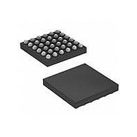
MAX97000EWA+T Maxim Integrated Products, MAX97000EWA+T Datasheet - Page 7

MAX97000EWA+T
Manufacturer Part Number
MAX97000EWA+T
Description
IC AUDIO SUBSYSTEM 25WLP
Manufacturer
Maxim Integrated Products
Series
DirectDrive™r
Type
Class Dr
Datasheet
1.MAX97000EWAT.pdf
(34 pages)
Specifications of MAX97000EWA+T
Output Type
1-Channel (Mono) with Stereo Headphones
Max Output Power X Channels @ Load
930mW x 1 @ 8 Ohm; 40mW x 2 @ 16 Ohm
Voltage - Supply
2.7 V ~ 5.5 V
Features
Depop, Differential Inputs, I²C, Mute, Shutdown, Volume Control
Mounting Type
Surface Mount
Package / Case
25-WLP
Product
Class-D
Output Power
725 mW
Available Set Gain
12 dB
Common Mode Rejection Ratio (min)
32 dB to 55 dB
Thd Plus Noise
0.05 %
Operating Supply Voltage
2.7 V to 5.5 V
Supply Current
0.4 mA to 1.45 mA
Maximum Power Dissipation
850 mW
Maximum Operating Temperature
+ 80 C
Mounting Style
SMD/SMT
Audio Load Resistance
41.2 KOhms
Input Signal Type
Differential
Minimum Operating Temperature
- 40 C
Output Signal Type
Differential
Supply Voltage (max)
5.5 V
Supply Voltage (min)
2.7 V
Lead Free Status / RoHS Status
Lead free / RoHS Compliant
Other names
MAX97000EWA+T
ELECTRICAL_CHARACTERISTICS_(continued)
(V
HPLVOL = HPRVOL= SPKVOL = 0dB, speaker loads (Z
nected from HPL or HPR to GND. SDA and SCL pullup voltage = 1.8V. Z
= 1FF. T
CHARGE_PUMP
Charge-Pump Frequency
Positive Output Voltage
Negative Output Voltage
Headphone Output Voltage
Threshold
Mode Transition Timeouts
HEADPHONE_AMPLIFIERS
Output Offset Voltage
Click-and-Pop Level
Power-Supply Rejection Ratio
Output Power
Channel-to-Channel Gain
Tracking
LDOIN
A
= V
PARAMETER
= T
PVDD
MIN
Speaker and Class H Headphone Amplifier
to T
= V
SHDN
MAX
, unless otherwise noted. Typical values are at T
= 3.7V, V
Audio Subsystem with Mono Class D
SYMBOL
V
V
PSRR
HPVDD
P
HPVSS
V
V
V
K
GND
OUT
TH1
TH2
OS
CP
= V
V
V
V
V
V
V
V
Output voltage at which the charge pump
switches between fast and slow clock
Output voltage at which the charge pump
switches modes, V
Time it takes for the charge pump to
transition from invert to split mode
Time it takes for the charge pump to
transition from split to invert mode
T
T
IN_DIFF = 0
Peak voltage, T
+25NC, A-weighted, 32
samples per second,
volume at mute
(Note 2)
T
THD+N = 1%,
f = 1kHz
T
maximum, HPLMIX = 0x01, HPRMIX = 0x02,
IN_DIFF = 0
PGND
A
A
A
A
HPL
HPL
HPL
HPL
HPL
HPL
HPL
= +25NC volume at mute
= +25NC, HP_VOL = 0dB, HP_MIX = 0x1,
= +25NC (Note 2)
= +25NC, HPL to HPR, volume at
, V
, V
, V
, V
= V
= V
= V
= 0V. Input signal applied at INA configured single-ended, preamp gain = 0dB,
HPR
HPR
HPR
HPR
HPR
HPR
HPR
SPK
> V
< V
> V
< V
= 0V
= 0.2V
= 0.5V
A
) connected between OUTP and OUTN. Headphone loads (R
CONDITIONS
TH
TH
TH
TH
=
OUT
Into shutdown
Out of shutdown
V
f = 217Hz,
V
f = 1kHz,
V
f = 20kHz,
V
R
R
R
LPMODE = 1,
LP gain = 3dB
rising or falling
LDOIN
RIPPLE
RIPPLE
RIPPLE
HP
HP
HP
SPK
= 16I
= 32I
= 32I,
A
= 2.5V to 5.5V
= +25NC.) (Note 1)
= J, R
= 200mV
= 200mV
= 200mV
HP
P-P
P-P
P-P
= J. C
C1P-C1N
MIN
0.40
0.1
80
70
= C
Q0.15
TYP
0.16
0.46
-1.8
-0.9
Q0.5
Q0.3
665
500
1.8
0.9
83
32
20
-74
-74
85
84
80
62
40
23
34
HPVDD
= C
MAX
Q0.6
Q2.5
0.21
0.52
85
HPVSS
HP
UNITS
= C
dBV
kHz
mW
mV
ms
dB
) con-
Fs
%
V
V
V
BIAS
7


