TDA7350A STMicroelectronics, TDA7350A Datasheet - Page 17
TDA7350A
Manufacturer Part Number
TDA7350A
Description
IC AMP AUDIO PWR 22W MULTIWATT11
Manufacturer
STMicroelectronics
Type
Class ABr
Datasheet
1.TDA7350A.pdf
(23 pages)
Specifications of TDA7350A
Output Type
1-Channel (Mono) or 2-Channel (Stereo)
Max Output Power X Channels @ Load
22W x 1 @ 3.2 Ohm; 11W x 2 @ 2 Ohm
Voltage - Supply
8 V ~ 18 V
Features
Depop, Short-Circuit and Thermal Protection, Standby
Mounting Type
Through Hole
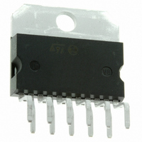
Package / Case
Multiwatt-11 (Vertical, Bent and Staggered Leads)
Lead Free Status / RoHS Status
Contains lead / RoHS non-compliant
Other names
497-3972-5
Available stocks
Company
Part Number
Manufacturer
Quantity
Price


If the voltage present across the load becomes rapidly zero (due to the fast switch off) a small pop occurs,
depending also on Cout,Rload.
The parameters that set the switch off time constant of the st-by pin are:
The time constant is given by :
T ≈ Csvr · 2000Ω // Rext + Cst-by · 2500Ω // Rext
The suggested time constants are :
T > 120ms with C
T > 170ms with C
If Rext is too low the Csvr can become too high and a different approach may be useful (see next section).
Figg 43, 44 show some types of electronic switches (µP compatible) suitable for supplying the st-by pin (it
is important that Qsw is able to saturate with V
Also for turn off pop the bridge configuration is superior, in particular the st-by pin can go low faster.
5.4 Global Approach to Solving Pop Problem by Using the Muting/Turn On Delay Function
In the real case turn-on and turn-off pop problems are generated not only by the power amplifier, but also
(very often) by preamplifiers,tone controls, radios etc. and transmitted by the power amplifier to the loud-
speaker.
A simple approach to solving these problems is to use the mute characteristics of the TDA7350A. If the
SVR pin is at a voltage below 1.5 V, the mute attenuation (typ)is 30dB .The amplifier is in play mode when
Vsvr overcomes 3.5 V.
With the circuit of fig 45 we can mute the amplifier for a time Ton after switch-on and for a time Toff after
switch-off. During this period the circuitry that precedes the power amplifier can produce spurious spikes
that are not transmitted to the loudspeaker.
This can give back a very simple design of this circuitry from the pop point of view. A timing diagram of
this circuit is illustrated in fig 46.
Other advantages of this circuit are:
Figure 43.
– A reduced time constant allowance of stand-by pin turn off. Consequently it is possible to drive all the
– A better turn-off noise with signal on the output. To drive two stereo amplifiers with this circuit it is
car-radio with the signal that drives this pin.
possible to use the circuit of fig 47.
■
■
■
the st-by capacitor (Cst-by)
the SVR capacitor (Csvr)
resistors connected from st-by pin to ground (Rext)
out
out
=1000µF, R
= 2200µF, R
L
L
= 4ohm,stereo
= 4ohm,stereo
CE
≤ 150mV).
TDA7350A
17/23
Related parts for TDA7350A
Image
Part Number
Description
Manufacturer
Datasheet
Request
R

Part Number:
Description:
STMicroelectronics [RIPPLE-CARRY BINARY COUNTER/DIVIDERS]
Manufacturer:
STMicroelectronics
Datasheet:
Part Number:
Description:
STMicroelectronics [LIQUID-CRYSTAL DISPLAY DRIVERS]
Manufacturer:
STMicroelectronics
Datasheet:

Part Number:
Description:
BOARD EVAL FOR MEMS SENSORS
Manufacturer:
STMicroelectronics
Datasheet:
Part Number:
Description:
NPN TRANSISTOR POWER MODULE
Manufacturer:
STMicroelectronics
Datasheet:
Part Number:
Description:
TURBOSWITCH ULTRA-FAST HIGH VOLTAGE DIODE
Manufacturer:
STMicroelectronics
Datasheet:
Part Number:
Description:
Manufacturer:
STMicroelectronics
Datasheet:
Part Number:
Description:
DIODE / SCR MODULE
Manufacturer:
STMicroelectronics
Datasheet:
Part Number:
Description:
DIODE / SCR MODULE
Manufacturer:
STMicroelectronics
Datasheet:
Part Number:
Description:
Search -----> STE16N100
Manufacturer:
STMicroelectronics
Datasheet:
Part Number:
Description:
Search ---> STE53NA50
Manufacturer:
STMicroelectronics
Datasheet:
Part Number:
Description:
NPN Transistor Power Module
Manufacturer:
STMicroelectronics
Datasheet:
Part Number:
Description:
DIODE / SCR MODULE
Manufacturer:
STMicroelectronics
Datasheet: