STA540 STMicroelectronics, STA540 Datasheet - Page 15
STA540
Manufacturer Part Number
STA540
Description
IC AMP AUD DUAL/QUAD MULTIWATT15
Manufacturer
STMicroelectronics
Type
Class ABr
Datasheet
1.STA540.pdf
(23 pages)
Specifications of STA540
Output Type
2-Channel (Stereo) or 4-Channel (Quad)
Max Output Power X Channels @ Load
38W x 2 @ 4 Ohm; 16W x 4 @ 4 Ohm
Voltage - Supply
8 V ~ 22 V
Features
Short-Circuit and Thermal Protection, Standby
Mounting Type
Through Hole
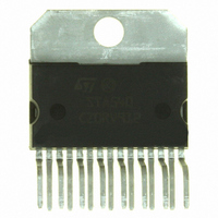
Package / Case
Multiwatt-15 (Vertical, Bent and Staggered Leads)
Amplifier Class
AB
No. Of Channels
4
Output Power
24W
Supply Voltage Range
8V To 22V
Thd + N
0.02% @ 4W, 4ohm, VS=14.4V
Load Impedance
8ohm
Operating Temperature Range
-40°C To +150°C
Rohs Compliant
Yes
Lead Free Status / RoHS Status
Lead free / RoHS Compliant
Other names
497-8880-5
Available stocks
Company
Part Number
Manufacturer
Quantity
Price
Company:

Part Number:
STA540
Manufacturer:
FOXCONN
Quantity:
2 300
Part Number:
STA540
Manufacturer:
ST
Quantity:
20 000
Company:
Part Number:
STA540SA
Manufacturer:
ST
Quantity:
12 000
Part Number:
STA540SA
Manufacturer:
ST
Quantity:
20 000
Part Number:
STA540SAN
Manufacturer:
ST
Quantity:
20 000


STA540
6
6.1
6.2
6.3
6.4
6.5
Practical information
Highly flexible amplifier configuration
The availability of four independent channels makes it possible to accomplish several kinds
of applications ranging from four speakers stereo (F/R) to two-speaker bridge solutions.
When working with single-ended configurations, the polarity of the speakers driven by the
inverting amplifier must be reversed with respect to those driven by non-inverting channels.
This is to avoid phase irregularities causing sound alterations especially during the
reproduction of low frequencies.
Easy single-ended to bridge transition
The change from single-ended to bridge configuration is made simple by connecting the two
inputs together and also the speaker directly between the two outputs (no need for
additional external components, in fact the output DC blocking capacitors are eliminated).
However, take care to use an inverting/non-inverting amplifier pair.
Internally fixed gain
The advantages in internally fixing the gain (to 20 dB in single-ended configuration and to
26 dB in bridge configuration) are:
"
"
Silent turn on/off and muting/standby function
The standby mode can be easily activated by means of a CMOS logic level applied to
pin ST-BY through a RC filter.
Under standby conditions, the device is turned off completely (supply current = 1 mA typical,
output attenuation = 80 dB minimum).
All on/off operations are virtually pop-free. Furthermore, at turn-on the device stays in mute
condition for a time determined by the value of the SVR capacitor. This prevents transients,
coming from previous stages, from producing unpleasant acoustic effects at the speakers.
Driving circuit for standby mode
Some precautions need to be taken when designing the driving circuit for pin 7, ST-BY. For
instance, the pin cannot be directly driven by a voltage source having a current capability
higher than 5 mA. In practical cases a series resistance must be inserted, giving it the
double purpose of limiting the current at pin 7 and to smooth down the standby on/off
transitions. And, when done in combination with a capacitor, prevents output pop.
A capacitor of at least 100 nF from pin 7 to S-GND, with no resistance in between, is
necessary to ensure correct turn-on.
components and space saving,
output noise, supply voltage rejection and distortion optimization.
Practical information
15/23
Related parts for STA540
Image
Part Number
Description
Manufacturer
Datasheet
Request
R

Part Number:
Description:
STMicroelectronics [RIPPLE-CARRY BINARY COUNTER/DIVIDERS]
Manufacturer:
STMicroelectronics
Datasheet:
Part Number:
Description:
STMicroelectronics [LIQUID-CRYSTAL DISPLAY DRIVERS]
Manufacturer:
STMicroelectronics
Datasheet:

Part Number:
Description:
BOARD EVAL FOR MEMS SENSORS
Manufacturer:
STMicroelectronics
Datasheet:
Part Number:
Description:
NPN TRANSISTOR POWER MODULE
Manufacturer:
STMicroelectronics
Datasheet:
Part Number:
Description:
TURBOSWITCH ULTRA-FAST HIGH VOLTAGE DIODE
Manufacturer:
STMicroelectronics
Datasheet:
Part Number:
Description:
Manufacturer:
STMicroelectronics
Datasheet:
Part Number:
Description:
DIODE / SCR MODULE
Manufacturer:
STMicroelectronics
Datasheet:
Part Number:
Description:
DIODE / SCR MODULE
Manufacturer:
STMicroelectronics
Datasheet:
Part Number:
Description:
Search -----> STE16N100
Manufacturer:
STMicroelectronics
Datasheet:
Part Number:
Description:
Search ---> STE53NA50
Manufacturer:
STMicroelectronics
Datasheet:
Part Number:
Description:
NPN Transistor Power Module
Manufacturer:
STMicroelectronics
Datasheet:
Part Number:
Description:
DIODE / SCR MODULE
Manufacturer:
STMicroelectronics
Datasheet: