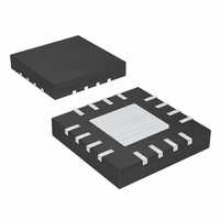
MAX9715ETE+ Maxim Integrated Products, MAX9715ETE+ Datasheet - Page 9

MAX9715ETE+
Manufacturer Part Number
MAX9715ETE+
Description
IC AMP AUDIO PWR 2.8W D 16TQFN
Manufacturer
Maxim Integrated Products
Type
Class Dr
Datasheet
1.MAX9715ETE.pdf
(13 pages)
Specifications of MAX9715ETE+
Output Type
2-Channel (Stereo)
Max Output Power X Channels @ Load
2.8W x 2 @ 4 Ohm
Voltage - Supply
4.5 V ~ 5.5 V
Features
Depop, Short-Circuit and Thermal Protection, Shutdown
Mounting Type
Surface Mount
Package / Case
16-TQFN Exposed Pad
Product
Class-D
Output Power
2.8 W
Thd Plus Noise
0.06 %
Operating Supply Voltage
5 V
Supply Current
12.8 mA
Maximum Power Dissipation
1666 mW
Maximum Operating Temperature
+ 85 C
Mounting Style
SMD/SMT
Minimum Operating Temperature
- 40 C
Supply Voltage (max)
5.5 V
Supply Voltage (min)
4.5 V
Amplifier Class
D
No. Of Channels
2
Supply Voltage Range
4.5V To 5.5V
Load Impedance
4ohm
Operating Temperature Range
-40°C To +85°C
Amplifier Case Style
TQFN
Rohs Compliant
Yes
Lead Free Status / RoHS Status
Lead free / RoHS Compliant
Voice coil movement due to the square-wave frequency
is very small because the switching frequency of the
MAX9715 is well beyond the bandwidth of most speak-
ers. Although this movement is small, a speaker not
designed to handle the additional power may be
damaged. Use a speaker with a series inductance
> 30μH for optimum efficiency. Typical 8Ω speakers
exhibit series inductances in the 30μH to 100μH range.
The highest efficiency is achieved with speaker induc-
tances > 60μH.
The input capacitor (C
input resistance (R
removes the DC bias from an incoming signal (see the
Typical Application Circuit ). The AC-coupling capacitor
allows the amplifier to bias the signal to an optimum DC
level. Assuming zero source impedance, the -3dB point
of the highpass filter is given by:
Figure 4. Optional Speaker Amplifier Output Filter—Guidelines for FCC Compliance
<75mm OF SPEAKER CABLE.
MAX9715
TYPICAL APPLICATION
OUTR+
OUTL+
OUTL-
OUTR-
(a)
f
2.8W, Low-EMI, Stereo, Filterless Class D
−
3
_______________________________________________________________________________________
dB
IN
IN
=
), forms a highpass filter that
), in conjunction with the amplifier
2π
×
Component Selection
R
IN
1
MAX9715
×
C
IN
APPLICATIONS USING CABLE LENGTHS
OUTR+
OUTL+
OUTR-
OUTL-
COMMON-MODE CHOKE FOR
GREATER THAN 150mm.
Input Filter
(b)
R
in the Electrical Characteristics table. Choose C
f
Setting f
response. Use capacitors with low-voltage coefficient
dielectrics, such as tantalum or aluminum electrolytic.
Capacitors with high-voltage coefficients, such as ceram-
ics, may result in increased distortion at low frequencies.
The inability of small diaphragm speakers to reproduce
low frequencies can be exploited to improve click-and-
pop performance. Set the cutoff frequency of the
MAX9715’s input highpass filter to match the speaker’s
frequency response. Doing so will allow for smaller C
values and reduce click-and-pop.
The MAX9715 speaker amplifiers do not require output
filters. However, output filtering can be used if a design
is failing radiated emissions due to board layout, cable
length, or the circuit is near EMI-sensitive devices. Use
a ferrite bead filter or a common-mode choke when radi-
ated frequencies above 10MHz are of concern. Use an
LC filter when radiated frequencies below 10MHz are of
concern, or when long cables (>75mm) connect the
amplifier to the speaker. Figure 4 shows possible output
filter connections.
-3dB
IN
is the amplifier’s internal input resistance value given
is well below the lowest frequency of interest.
-3dB
MAX9715
too high affects the amplifier’s low-frequency
OUTR+
OUTL+
OUTR-
OUTL-
Audio Amplifier
LC FILTER WHEN USING LONG CABLE
LENGTHS OR IN APPLICATIONS
THAT ARE SENSITIVE TO EMI.
(c)
Output Filter
IN
so
IN
9


