LME49811TB/NOPB National Semiconductor, LME49811TB/NOPB Datasheet - Page 5
LME49811TB/NOPB
Manufacturer Part Number
LME49811TB/NOPB
Description
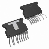
IC AMP AUDIO PWR 500W TO247-15
Manufacturer
National Semiconductor
Type
Class ABr
Datasheet
1.LME49811TBNOPB.pdf
(18 pages)
Specifications of LME49811TB/NOPB
Output Type
1-Channel (Mono)
Max Output Power X Channels @ Load
500W x 1 @ 8 Ohm
Voltage - Supply
40 V ~ 200 V, ±20 V ~ 100 V
Features
Shutdown, Thermal Protection
Mounting Type
Through Hole
Package / Case
TO-247-15 (Bent and Staggered Leads)
Amplifier Class
AB
No. Of Channels
1
Supply Voltage Range
± 20V To ± 100V
Load Impedance
8ohm
Operating Temperature Range
-40°C To +85°C
Amplifier Case Style
TO-247
No. Of Pins
15
Rohs Compliant
Yes
Lead Free Status / RoHS Status
Lead free / RoHS Compliant
Other names
LME49811TB
Available stocks
Company
Part Number
Manufacturer
Quantity
Price
Company:

Part Number:
LME49811TB/NOPB
Manufacturer:
TE
Quantity:
1 200


I
I
THD+N
A
A
V
V
I
I
SR
V
I
PSRR
CC
EE
OUT
SD
B
V
V
OM
NOISE
OS
Electrical Characteristics +V
The following specifications apply for I
Note 1: “Absolute Maximum Ratings” indicate limits beyond which damage to the device may occur, including inoperability and degradation of device reliability
and/or performance. Functional operation of the device and/or non-degradation at the Absolute Maximum Ratings or other conditions beyond those indicated in
the Recommended Operating Conditions is not implied. The Recommended Operating Conditions indicate conditions at which the device is functional and the
device should not be operated beyond such conditions. All voltages are measured with respect to the ground pin, unless otherwise specified
Note 2: The Electrical Characteristics tables list guaranteed specifications under the listed Recommended Operating Conditions except as otherwise modified
or specified by the Electrical Characteristics Conditions and/or Notes. Typical specifications are estimations only and are not guaranteed.
Note 3: The maximum power dissipation must be derated at elevated temperatures and is dictated by T
allowable power dissipation is P
Note 4: Human body model, applicable std. JESD22-A114C.
Note 5: Machine model, applicable std. JESD22-A115-A.
Note 6: Typical values represent most likely parametric norms at T
characterization and are not guaranteed.
Note 7: Datasheet min/max specification limits are guaranteed by test or statistical analysis.
Note 8: The maximum operating junction temperature is 150°C.
Note 9: The Data taken with Bandwidth = 30kHz, A
Symbol
Total Quiescent Power Supply
Current
Total Quiescent Power Supply
Current
Total Harmonic Distortion +
Noise
Closed Loop Voltage Gain
Open Loop Gain
Output Voltage Swing
Output Noise
Output Current
Current into Shutdown Pin
Slew Rate
Input Offset Voltage
Input Bias Current
Power Supply Rejection Ratio
Parameter
DMAX
= (T
JMAX
- T
SD
A
) / θ
= 1.5mA, Figure 1, unless otherwise specified. Limits apply for T
V
= 29dB, C
JA
or the number given in Absolute Maximum Ratings, whichever is lower.
CC
V
V
No load, A
V
V
f = DC
THD+N = 0.05%, Freq = 20Hz to 20kHz
LPF = 30kHz, Av = 29dB
A-weighted
Outputs Shorted
To put part in “play” mode
V
Outputs shorted
V
V
f = DC, Input Referred
CM
CM
OUT
IN
IN
CM
CM
C
= 1mV
= 1.2V
= 30pF, and T
= –V
= 0V, V
= 0V, V
= 0V, I
= 0V, I
A
= 30V
= +25ºC, and at the Recommended Operation Conditions at the time of product
RMS
P-P
V
O
O
EE
RMS
O
O
= 30dB
, f = 10kHz square Wave,
= 0mA
= 0mA
= 0V, I
= 0V, I
, f = 1kHz
5
, f = 1kHz
A
Conditions
= 100V
= 25°C except where specified.
O
O
= 0A
= 0A
(Note
JMAX
1,
, θ
Note
JA
, and the ambient temperature, T
2)
(Note
0.00035
Typical
120
100
100
115
1.5
17
19
93
68
70
17
9
1
LME49811
6)
A
(Note
= 25°C.
Limit
0.001
180
105
22
24
26
14
7
1
2
3
7)
A
. The maximum
www.national.com
V/μs (min)
mA (max)
mA (max)
mA (max)
mV (max)
μV (max)
nA (max)
% (max)
dB (min)
mA(min)
mA(min)
dB (min)
(Limits)
Units
V
dB
dB
μV
RMS
Related parts for LME49811TB/NOPB
Image
Part Number
Description
Manufacturer
Datasheet
Request
R

Part Number:
Description:
Lme49811 Audio Power Amplifier Series High Fidelity 200 Volt Power Amplifier Input Stage With Shutdown
Manufacturer:
National Semiconductor Corporation
Datasheet:

Part Number:
Description:
National Semiconductor [8-Bit D/A Converter]
Manufacturer:
National Semiconductor
Datasheet:
Part Number:
Description:
National Semiconductor [Media Coprocessor]
Manufacturer:
National Semiconductor
Datasheet:
Part Number:
Description:
Digitally Controlled Tone and Volume Circuit with Stereo Audio Power Amplifier, Microphone Preamp Stage and National 3D Sound
Manufacturer:
National Semiconductor
Datasheet:
Part Number:
Description:
Digitally Controlled Tone and Volume Circuit with Stereo Audio Power Amplifier, Microphone Preamp Stage and National 3D Sound
Manufacturer:
National Semiconductor
Datasheet:
Part Number:
Description:
AC97 Rev 2 Codec with Sample Rate Conversion and National 3D Sound
Manufacturer:
National Semiconductor
Part Number:
Description:
Manufacturer:
National Semiconductor
Datasheet:
Part Number:
Description:
Manufacturer:
National Semiconductor
Datasheet:
Part Number:
Description:
General Purpose, Low Voltage, Low Power, Rail-to-Rail Output Operational Amplifiers
Manufacturer:
National Semiconductor
Datasheet:
Part Number:
Description:
8-bit 20 MSPS flash A/D converter.
Manufacturer:
National Semiconductor
Datasheet:
Part Number:
Description:
Low Noise Quad Operational Amplifier
Manufacturer:
National Semiconductor
Datasheet:
Part Number:
Description:
Quad Differential Line Receivers
Manufacturer:
National Semiconductor
Datasheet:
Part Number:
Description:
Quad High Speed Trapezoidal? Bus Transceiver
Manufacturer:
National Semiconductor
Datasheet:
Part Number:
Description:
Dual Line Receiver
Manufacturer:
National Semiconductor
Datasheet: