LM4985TM/NOPB National Semiconductor, LM4985TM/NOPB Datasheet - Page 25
LM4985TM/NOPB
Manufacturer Part Number
LM4985TM/NOPB
Description
IC AMP AUDIO PWR .135W AB 12USMD
Manufacturer
National Semiconductor
Series
Boomer®r
Type
Class ABr
Datasheet
1.LM4985TMNOPB.pdf
(29 pages)
Specifications of LM4985TM/NOPB
Output Type
Headphones, 2-Channel (Stereo)
Max Output Power X Channels @ Load
135mW x 2 @ 16 Ohm
Voltage - Supply
2.3 V ~ 5.5 V
Features
I²C, Shutdown, Thermal Protection, Volume Control
Mounting Type
Surface Mount
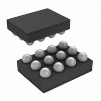
Package / Case
12-MicroSMD
Operational Class
Class-AB
Audio Amplifier Output Configuration
2-Channel Stereo
Output Power (typ)
135x2@16OhmW
Audio Amplifier Function
Headphone
Single Supply Voltage (typ)
3/5V
Dual Supply Voltage (typ)
Not RequiredV
Power Supply Requirement
Single
Rail/rail I/o Type
No
Power Supply Rejection Ratio
77dB
Single Supply Voltage (min)
2.3V
Single Supply Voltage (max)
5.5V
Dual Supply Voltage (min)
Not RequiredV
Dual Supply Voltage (max)
Not RequiredV
Operating Temp Range
-40C to 85C
Operating Temperature Classification
Industrial
Mounting
Surface Mount
Pin Count
12
For Use With
LM4985TMEVAL - BOARD EVALUATION LM4985TM
Lead Free Status / RoHS Status
Lead free / RoHS Compliant
Other names
LM4985TMTR


Application Information
coupling capacitor requires more charge to reach its quies-
cent DC voltage. This charge comes from the output via the
feedback Thus, by minimizing the capacitor size based on
necessary low frequency response, turn-on time can be
minimized. A small value of C
0.68µF), is recommended.
MAXIMIZING OCL MODE CHANNEL-to-CHANNEL
SEPARATION
The OCL mode AC ground return (CNT_GND pin) is shared
by both amplifiers. As such, any resistance between the
CNT_GND pin and the load will create a voltage divider with
respect to the load resistance. In a typical circuit, the amount
of CNT_GND resistance can be very small, but still signifi-
cant. It is significant because of the relatively low load im-
pedances for which the LM4985 was designed to drive: 16Ω
i
(in the range of 0.22µF to
(Continued)
25
to 32Ω. The ratio of this voltage divider will determine the
magnitude of any residual signal present at the CNT_GND
pin. It is this residual signal that leads to channel-to-channel
separation (crosstalk) degradation.
For example, for a 60dB channel-to-channel separation
while driving a 16Ω load, the resistance between the
LM4985’s CNT_GND pin and the load must be less than
16mΩ. This is achieved by ensuring that the trace that
connects the CNT_GND pin to the headphone jack sleeve
should be as short and massive as possible, given the
physical constraints of any specific printed circuit board lay-
out and design.
DEMONSTRATION BOARD AND PCB LAYOUT
Information concerning PCB layout considerations and dem-
onstration board use and performance is found in Application
Note AN-1452.
www.national.com
Related parts for LM4985TM/NOPB
Image
Part Number
Description
Manufacturer
Datasheet
Request
R

Part Number:
Description:
National Semiconductor [8-Bit D/A Converter]
Manufacturer:
National Semiconductor
Datasheet:
Part Number:
Description:
National Semiconductor [Media Coprocessor]
Manufacturer:
National Semiconductor
Datasheet:
Part Number:
Description:
Digitally Controlled Tone and Volume Circuit with Stereo Audio Power Amplifier, Microphone Preamp Stage and National 3D Sound
Manufacturer:
National Semiconductor
Datasheet:
Part Number:
Description:
Digitally Controlled Tone and Volume Circuit with Stereo Audio Power Amplifier, Microphone Preamp Stage and National 3D Sound
Manufacturer:
National Semiconductor
Datasheet:
Part Number:
Description:
AC97 Rev 2 Codec with Sample Rate Conversion and National 3D Sound
Manufacturer:
National Semiconductor
Part Number:
Description:
Manufacturer:
National Semiconductor
Datasheet:
Part Number:
Description:
Manufacturer:
National Semiconductor
Datasheet:
Part Number:
Description:
General Purpose, Low Voltage, Low Power, Rail-to-Rail Output Operational Amplifiers
Manufacturer:
National Semiconductor
Datasheet:
Part Number:
Description:
8-bit 20 MSPS flash A/D converter.
Manufacturer:
National Semiconductor
Datasheet:
Part Number:
Description:
Low Noise Quad Operational Amplifier
Manufacturer:
National Semiconductor
Datasheet:
Part Number:
Description:
Quad Differential Line Receivers
Manufacturer:
National Semiconductor
Datasheet:
Part Number:
Description:
Quad High Speed Trapezoidal? Bus Transceiver
Manufacturer:
National Semiconductor
Datasheet:
Part Number:
Description:
Dual Line Receiver
Manufacturer:
National Semiconductor
Datasheet:
Part Number:
Description:
TTL to 10k ECL Level Translator with Latch
Manufacturer:
National Semiconductor
Datasheet: