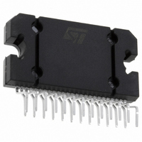
TDA7454 STMicroelectronics, TDA7454 Datasheet

TDA7454
Specifications of TDA7454
Available stocks
Related parts for TDA7454
TDA7454 Summary of contents
Page 1
... HIGH EFFICIENCY QUAD BRIDGE MULTIPOWER BCD TECHNOLOGY LOUDSPEAKER DC CURRENT ESD DESCRIPTION The TDA7454 is a new BCD technology QUAD BRIDGE type of car radio amplifier in Flexiwatt25 package specially intended for car radio applications. Among the features, its superior efficiency per- formance coming from the internal exclusive ...
Page 2
... TDA7454 ABSOLUTE MAXIMUM RATINGS Symbol V Operating Supply Voltage Supply Voltage S V Peak Supply Voltage (for t = 50ms) peak I Output Peak Current (not repetitive t = 100 Output Peak Current (repetitive f > 10Hz Power Dissipation T tot Storage and Junction Temperature stg j THERMAL DATA Symbol R Thermal Resistance Junction-case ...
Page 3
... 1W; HE MODE 10W; HE MODE MODE MODE 15W 1KHz to 10KHz R = 600 300Hz 1Vrms 100 ; g (–3dB 18V S max Standard BTL Mode Op pin 16 High Efficiency Mode (V ) pin 16 CD off 10W Omin CD on: THD = 5% TDA7454 = 1KHz; L Min. Typ. Max. Unit 140 250 0.03 0.3 % 0.04 ...
Page 4
... TDA7454 Figure 1: Standard Test and Application Circuit. R1 ST-BY 10K 0 MUTE 10K 0.22 F S-GND (*) OPEN = STANDARD BTL CLOSED=HI-EFF BTL 4/ 0.1 F 2200 F Vcc1 Vcc2 TDA7454 SVR (*) C5 SW1 100 F CLIP DET OUT OUT OUT OUT TAB D95AU416 ...
Page 5
... Figure 2: P.C.B. and components layout of fig. 1 circuit. (1.25 :1 scale) COMPONENTS & TOP COPPER LAYER BOTTOM COPPER LAYER TDA7454 5/13 ...
Page 6
... TDA7454 Figure 3: Quiescent Current vs. Supply Voltage Id (mA) 240 200 Ohm 160 120 (V) Figure 5: Max. Output Power vs. Supply Voltage Po ( RL= 4 Ohm KHz (V) Figure 7: Max. Output Power vs. Supply Voltage Po ( RL= 2 Ohm KHz (V) 6/13 Figure 4: Output Power vs. Supply Voltage Po ( Figure 6: Output Power vs. Supply Voltage ...
Page 7
... Figure 12: Supply Voltage Rejection vs. Fre- SVR (dB) 100 90 Vripple= 1 Vrms 1000 10000 10 Figure 14: Power Dissipation and Efficiency vs. Ptot ( 0.1 10000 Po 20,000 Hz 0.5 1 1.5 2 2.5 3 3.5 4 Vpin22 (V) quency Rg= 0 100 1000 f (Hz) Output Power Vs= 14 Ohm KHz HI-EFF MODE n Ptot 1 Po (W) TDA7454 4.5 5 10000 n (%) 7/13 ...
Page 8
... THD that the amplifier 8/13 can deliver. This holds true even at high volumes and frequent clipping occurrence. Applied to the TDA7454 (rated power= 25 W), this will result into an average output level of 2 sine-wave operation, region where the dissipated power is about 50 % less than that of a traditional amplifier of equivalent power class (see TDA7454 vs ...
Page 9
... STANDARD QUAD SINGLE-ENDED MODE 150 Vref STD/HI-EFF (pin 16) NTC t(Theatsink) TDA7454 can be set to operate as a STANDARD BRIDGE, turning into HIGH EFFICIENCY mode only if overheating is recognised in the critical spot, thus reducing the overall temperature in the circuit. CLIPPING DETECTOR / DIAGNOSTIC (pin 25) The TDA7454 is equipped with a diagnostic func- tion whose output is available at pin 25 ...
Page 10
... Short-circuits across the speakers will give inter- mittent (pulsed) signalling, output voltage amplitude. External Layout Grounding The 4 bridge stuctures have independent power ground accesses (pins 2,8,18,24), while the sig- nal ground is common to all of them (pin 13). The Figure 15: TDA7454’s Half Structure + INF SW1 ...
Page 11
... Figure 18: Power Dissipation (Sine-Wave) Pdiss ( 14 Ohm 35 CLASS- TDA7454 each channel (W) Figure 19: Power Dissipation (Gaussian Signals) Pdiss ( 14 Ohm 0.1 Pout each channel (W) TDA7454 CLASS-AB TDA7454 1 10 11/13 ...
Page 12
... TDA7454 mm DIM. MIN. TYP. MAX. A 4.45 4.50 4.65 0.175 B 1.80 1.90 2.00 0.070 C 1.40 D 0.75 0.90 1.05 0.029 E 0.37 0.39 0.42 0.014 F (1) 0.57 G 0.80 1.00 1.20 0.031 G1 23.75 24.00 24.25 0.935 H (2) 28.90 29.23 29.30 1.138 H1 17.00 H2 12.80 H3 0.80 L (2) 22 ...
Page 13
... STMicroelectronics – Printed in Italy – All Rights Reserved Australia - Brazil - China - Finland - France - Germany - Hong Kong - India - Italy - Japan - Malaysia - Malta - Morocco - Singapore - Spain - Sweden - Switzerland - United Kingdom - U.S.A. The ST logo is a registered trademark of STMicroelectronics STMicroelectronics GROUP OF COMPANIES http://www.st.com TDA7454 13/13 ...


