TDA7265 STMicroelectronics, TDA7265 Datasheet - Page 8
TDA7265
Manufacturer Part Number
TDA7265
Description
IC AMP AUDIO PWR 25W MULTIWATT11
Manufacturer
STMicroelectronics
Type
Class ABr
Datasheet
1.TDA7265.pdf
(11 pages)
Specifications of TDA7265
Output Type
2-Channel (Stereo)
Max Output Power X Channels @ Load
25W x 2 @ 8 Ohm
Voltage - Supply
±5 V ~ 25 V
Features
Depop, Mute, Short-Circuit and Thermal Protection, Standby
Mounting Type
Through Hole
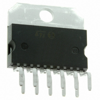
Package / Case
Multiwatt-11 (Vertical, Bent and Staggered Leads)
Amplifier Class
AB
No. Of Channels
2
Output Power
25W
Supply Voltage Range
± 5V To ± 25V
Load Impedance
4ohm
Operating Temperature Range
-20°C To +85°C
Amplifier Case Style
Multiwatt11
Rohs Compliant
Yes
Lead Free Status / RoHS Status
Lead free / RoHS Compliant
Other names
497-3960-5
Available stocks
Company
Part Number
Manufacturer
Quantity
Price
Company:

Part Number:
TDA7265
Manufacturer:
ST
Quantity:
15 000
Company:
Part Number:
TDA7265
Manufacturer:
ST
Quantity:
13 440
Part Number:
TDA7265
Manufacturer:
ST
Quantity:
20 000
Part Number:
TDA7265A
Manufacturer:
ST
Quantity:
20 000
Company:
Part Number:
TDA7265B
Manufacturer:
MPS
Quantity:
20 000
Part Number:
TDA7265B
Manufacturer:
ST
Quantity:
20 000


TDA7265
APPLICATIONS SUGGESTION
(Demo Board Schematic)
The recommended values of the external compo-
(*) Closed loop gain has to be => 25dB
MUTE, STAND-BY TRUTH TABLE
8/11
COMPONENTS
R7, R10
R5, R8
R6, R9
C1, C2
C4, C6
C5, C7
C8, C9
SW1
Dz
R1
R2
R3
R4
C3
Q1
B
B
A
A
RECOMMENDED
VALUE
1000 F
BC107
0.1 F
0.1 F
SW2
10K
15K
18K
15K
18K
560
4.7
5.1V
1 F
1 F
A
B
A
B
Mute Circuit
Mute Circuit
Mute Circuit
Mute Circuit
Closed Loop Gain
Setting (*)
Frequency Stability
Input DC
Decoupling
St-By/Mute Time
Constant
Supply Voltage
Bypass
Supply Voltage
Bypass
Frequency Stability
Mute Circuit
Mute Circuit
STAND-BY
STAND-BY
MUTE
PLAY
PURPOSE
nents are those shown are the demo board sche-
matic different values can be used: the following
table can help the designer.
RECOMMENDED VALUE
Increase of Dz
Biasing Current
V
V
V
Increase of Gain
Decrease of Gain
Danger of Oscillations
Larger On/Off Time
pin
pin
pin
# 5 Shifted Downward
# 5 Shifted Upward
# 5 Shifted Upward
LARGER THAN
RECOMMENDED VALUE
V
V
V
Higher Low Frequency
Cutoff
Smaller On/Off Time
Danger of Oscillations
Danger of Oscillations
Danger of Oscillations
pin
pin
pin
SMALLER THAN
# 5 Shifted Upward
# 5 Shifted Downward
# 5 Shifted Downward
Related parts for TDA7265
Image
Part Number
Description
Manufacturer
Datasheet
Request
R

Part Number:
Description:
STMicroelectronics [RIPPLE-CARRY BINARY COUNTER/DIVIDERS]
Manufacturer:
STMicroelectronics
Datasheet:
Part Number:
Description:
STMicroelectronics [LIQUID-CRYSTAL DISPLAY DRIVERS]
Manufacturer:
STMicroelectronics
Datasheet:

Part Number:
Description:
BOARD EVAL FOR MEMS SENSORS
Manufacturer:
STMicroelectronics
Datasheet:
Part Number:
Description:
NPN TRANSISTOR POWER MODULE
Manufacturer:
STMicroelectronics
Datasheet:
Part Number:
Description:
TURBOSWITCH ULTRA-FAST HIGH VOLTAGE DIODE
Manufacturer:
STMicroelectronics
Datasheet:
Part Number:
Description:
Manufacturer:
STMicroelectronics
Datasheet:
Part Number:
Description:
DIODE / SCR MODULE
Manufacturer:
STMicroelectronics
Datasheet:
Part Number:
Description:
DIODE / SCR MODULE
Manufacturer:
STMicroelectronics
Datasheet:
Part Number:
Description:
Search -----> STE16N100
Manufacturer:
STMicroelectronics
Datasheet:
Part Number:
Description:
Search ---> STE53NA50
Manufacturer:
STMicroelectronics
Datasheet:
Part Number:
Description:
NPN Transistor Power Module
Manufacturer:
STMicroelectronics
Datasheet:
Part Number:
Description:
DIODE / SCR MODULE
Manufacturer:
STMicroelectronics
Datasheet: