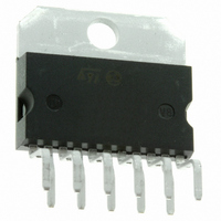
TDA7360 STMicroelectronics, TDA7360 Datasheet - Page 19

TDA7360
Manufacturer Part Number
TDA7360
Description
IC AMP AUDIO PWR 22W MULTIWATT11
Manufacturer
STMicroelectronics
Type
Class ABr
Datasheet
1.TDA7360.pdf
(30 pages)
Specifications of TDA7360
Output Type
1-Channel (Mono) or 2-Channel (Stereo)
Max Output Power X Channels @ Load
22W x 1 @ 3.2 Ohm; 12W x 2 @ 1.6 Ohm
Voltage - Supply
8 V ~ 18 V
Features
Depop, Short-Circuit and Thermal Protection, Standby
Mounting Type
Through Hole
Package / Case
Multiwatt-11 (Vertical, Bent and Staggered Leads)
Operational Class
Class-AB
Output Power (typ)
22W
Audio Amplifier Function
Speaker
Total Harmonic Distortion
0.05%%
Single Supply Voltage (typ)
9/12/15V
Dual Supply Voltage (typ)
Not RequiredV
Power Supply Requirement
Single
Power Dissipation
36W
Rail/rail I/o Type
No
Power Supply Rejection Ratio
62dB
Single Supply Voltage (min)
8V
Single Supply Voltage (max)
18V
Dual Supply Voltage (min)
Not RequiredV
Dual Supply Voltage (max)
Not RequiredV
Operating Temp Range
-40C to 150C
Operating Temperature Classification
Automotive
Mounting
Through Hole
Pin Count
11 +Tab
Package Type
MULTIWATT V
Lead Free Status / RoHS Status
Lead free / RoHS Compliant
Other names
497-3973-5
Available stocks
Company
Part Number
Manufacturer
Quantity
Price
Part Number:
TDA7360
Manufacturer:
ST
Quantity:
20 000
TDA7360
3.2.9
It is possible, controlling the amount of this local feedback, to force the loop gain (A. β) to
less than unity at frequencies for which the phase shift is 180°. This means that the output
buffer is intrinsically stable and not prone to oscillation.
Figure 33. The new output stage
In contrast, with the circuit of
frequencies is the use of an external RC network.
Figure 34. A classical output stage
Amplifier block diagram
The block diagram of each voltage amplifier is shown in
spread, the current in each final stage is kept low, with enough margin on the minimum,
below which cross-over distortion would appear.
Figure 35. Amplifier block diagram
Figure
Doc ID 1499 Rev 3
34, the solution adopted to reduce the gain at high
Figure
35. Regardless of production
General description
19/30


