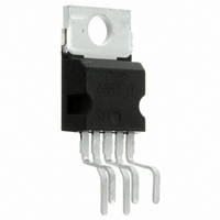
TDA2040V STMicroelectronics, TDA2040V Datasheet - Page 11

TDA2040V
Manufacturer Part Number
TDA2040V
Description
IC AMP AUDIO PWR HIFI PENTAWATT5
Manufacturer
STMicroelectronics
Type
Class ABr
Datasheet
1.TDA2040V.pdf
(16 pages)
Specifications of TDA2040V
Output Type
1-Channel (Mono)
Max Output Power X Channels @ Load
22W x 1 @ 4 Ohm
Voltage - Supply
5 V ~ 40 V, ±2.5 V ~ 20 V
Features
Short-Circuit and Thermal Protection
Mounting Type
Through Hole
Package / Case
Pentawatt-5 (Vertical, Bent and Staggered Leads)
Product
Class-AB
Output Power
22 W
Available Set Gain
80 dB
Thd Plus Noise
0.08 %
Operating Supply Voltage
20 V
Maximum Power Dissipation
25000 mW
Maximum Operating Temperature
+ 150 C
Mounting Style
Through Hole
Audio Load Resistance
8 Ohms
Dual Supply Voltage
+/- 3 V, +/- 5 V, +/- 9 V, +/- 12 V, +/- 15 V, +/- 18 V
Input Bias Current (max)
1 uA
Input Offset Voltage
20 mV
Input Signal Type
Differential
Minimum Operating Temperature
- 40 C
Output Signal Type
Single
Supply Type
Dual
Amplifier Class
AB
No. Of Channels
1
Supply Voltage Range
± 2.5V To ± 20V
Load Impedance
4ohm
Operating Temperature Range
-40°C To +150°C
Rohs Compliant
Yes
Dc
1141
Lead Free Status / RoHS Status
Lead free / RoHS Compliant
Other names
497-3027-5
Available stocks
Company
Part Number
Manufacturer
Quantity
Price
Company:
Part Number:
TDA2040V
Manufacturer:
KOA
Quantity:
460 000
TDA2040
3.2
Figure 21. Frequency response
Multiway speaker systems and active boxes
Multiway loudspeaker systems provide the best possible acoustic performance since each
loudspeaker is specially designed and optimized to handle a limited range of frequencies.
Commonly, these loudspeaker systems divide the audio spectrum into two, three or four
bands.
To maintain a flat frequency response over the hi-fi audio range the bands covered by each
loudspeaker must overlap slightly. Any imbalance between the loudspeakers produces
unacceptable results, therefore, it is important to ensure that each unit generates the correct
amount of acoustic energy for its segment of the audio spectrum. In this respect it is also
important to know the energy distribution of the music spectrum (see Figure 22) in order to
determine the cut-off frequencies of the crossover filters. As an example, a 100-W three-way
system with crossover frequencies of 400 Hz and 3 kHz would require 50 W for the woofer,
35 W for the midrange unit and 15 W for the tweeter.
Both active and passive filters can be used for crossovers but today active filters cost
significantly less than a good passive filter using air-cored inductors and non-electrolytic
capacitors. In addition, active filters do not suffer from the typical defects of passive filters:
Obviously, active crossovers can only be used if a power amplifier is provided for each drive
unit. This makes it particularly interesting and economically sound to use monolithic power
amplifiers.
In some applications, complex filters are not really necessary and simple RC low-pass and
high-pass networks (6 dB/octave) can be recommended. The results obtained are excellent
because this is the best type of audio filter and the only one free from phase and transient
distortion. The rather poor out of band attenuation of single RC filters means that the
loudspeaker must operate linearly well beyond the crossover frequency to avoid distortion.
power loss
increased impedance seen by the loudspeaker (lower damping)
difficulty of precise design due to variable loudspeaker impedance
Doc ID 1460 Rev 4
Figure 22. Power distribution vs frequency
Applications
11/16


