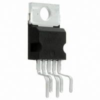
TDA2050V STMicroelectronics, TDA2050V Datasheet - Page 11

TDA2050V
Manufacturer Part Number
TDA2050V
Description
IC AMP AUDIO PWR HIFI PENTAWATT5
Manufacturer
STMicroelectronics
Type
Class ABr
Datasheet
1.TDA2050V.pdf
(13 pages)
Specifications of TDA2050V
Output Type
1-Channel (Mono)
Max Output Power X Channels @ Load
35W x 1 @ 4 Ohm
Voltage - Supply
9 V ~ 50 V, ±4.5 V ~ 25 V
Features
Short-Circuit and Thermal Protection
Mounting Type
Through Hole
Package / Case
Pentawatt-5 (Vertical, Bent and Staggered Leads)
Product
Class-AB
Output Power
50 W
Available Set Gain
80 dB
Thd Plus Noise
0.03 %
Operating Supply Voltage
25 V
Supply Current
90 mA
Maximum Power Dissipation
25000 mW
Maximum Operating Temperature
+ 150 C
Mounting Style
Through Hole
Audio Load Resistance
8 Ohms
Dual Supply Voltage
+/- 5 V, +/- 9 V, +/- 12 V, +/- 15 V, +/- 18 V, +/- 24 V
Input Bias Current (max)
0.5 uA
Input Offset Voltage
15 mV
Input Signal Type
Differential
Minimum Operating Temperature
- 40 C
Output Signal Type
Single
Supply Type
Dual
Amplifier Class
AB
No. Of Channels
1
Supply Voltage Range
± 4.5V To ± 25V
Load Impedance
4ohm
Operating Temperature Range
-40°C To +150°C
Rohs Compliant
Yes
Lead Free Status / RoHS Status
Lead free / RoHS Compliant
Other names
497-3028-5
Available stocks
Company
Part Number
Manufacturer
Quantity
Price
Company:
Part Number:
TDA2050V
Manufacturer:
MICRON
Quantity:
11 560
Part Number:
TDA2050V
Manufacturer:
ST
Quantity:
20 000
A circuit for generating the test signal is given in
fig. 19.
The load network consists of a 40 F capacitor, in
series with a 1 ohm resistor. The capacitor limits
the current due to the 20 Hz signal to a low value,
whereas for he short pulses the effective load im-
pedance is of the order of 1 ohm, and a high out-
put current is produced.
Using this signal and load network the measure-
ment may be made without causing excessive
dissipation in the amplifier. The dissipation in the
1 ohm resistor is much lower than a rated output
Figure 19: Test circuit for peak power measurement
power of the amplifier, because the duty-cycle of
the high output current is low.
By feeding the amplifier output voltage to the X-
plates of an oscilloscope, and the voltage across
the 1 ohm resistor (representing the output cur-
rent) to the Y=plates, it is possible to read on the
display the value of the maximum instantaneous
output power.
The result of this test applied at the TDA 2050 is:
PEAK POWER = 100W typ
TDA2050
11/13


