TDA2003H STMicroelectronics, TDA2003H Datasheet - Page 8
TDA2003H
Manufacturer Part Number
TDA2003H
Description
IC AMP AUDIO 12W MONO PENTAWATT5
Manufacturer
STMicroelectronics
Type
Class ABr
Datasheet
1.TDA2003H.pdf
(10 pages)
Specifications of TDA2003H
Output Type
1-Channel (Mono)
Max Output Power X Channels @ Load
12W x 1 @ 1.6 Ohm
Voltage - Supply
8 V ~ 18 V
Features
Short-Circuit and Thermal Protection
Mounting Type
Through Hole
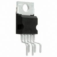
Package / Case
Pentawatt-5 (Horizontal, Bent and Staggered Leads)
Product
Class-AB
Output Power
12 W
Available Set Gain
80 dB
Thd Plus Noise
0.15 %
Operating Supply Voltage
9 V, 12 V, 15 V
Supply Current
3.5 A
Maximum Power Dissipation
20000 mW
Maximum Operating Temperature
+ 150 C
Mounting Style
Through Hole
Audio Load Resistance
4 Ohms
Input Signal Type
Single
Minimum Operating Temperature
- 40 C
Output Signal Type
Single
Supply Type
Single
Supply Voltage (max)
18 V
Supply Voltage (min)
8 V
Lead Free Status / RoHS Status
Lead free / RoHS Compliant
Other names
497-2161-5
Available stocks
Company
Part Number
Manufacturer
Quantity
Price

Company:
Part Number:
TDA2003H
Manufacturer:
LT
Quantity:
4 763
Part Number:
TDA2003H
Manufacturer:
ST
Quantity:
20 000
Company:
Part Number:
TDA2003H-LF
Manufacturer:
FSC
Quantity:
30 000
Part Number:
TDA2003HLG
Manufacturer:
ST
Quantity:
20 000


TDA2003
PRATICAL CONSIDERATION
Printed circuit board
The layout shown in fig. 17 is recommended. If
different layouts are used, the ground points of
input 1 and input 2 must be well decoupled from
the ground of the output through which a rather high
current flows.
Assembly suggestion
No electrical insulation is required between the
8/10
Component
C1
C2
C3
C4
C5
R1
R2
R3
C
R
X
X
Recommmended
(G
1000 F
470 F
2.2 F
0.1 F
0.1 F
v
value
2
2.2
-1) R2
20 R2
1
1
B R1
Input DC
decoupling
Ripple rejection
Supply bypassing
Output coupling to load
Frequency stability
Upper frequency cutoff
Setting of gain
Setting of gain
and SVR
Frequency stability
Upper frequency cutoff
Purpose
package and the heat-sink. Pin length should be as
short as possible. The soldering temperature must
not exceed 260 C for 12 seconds.
Application suggestions
The recommended component values are those
shown in the application circuits of fig. 16.
Different values can be used. The following table is
intended to aid the car-radio designer.
Lower bandwidth
Degradation of SVR
Danger of oscillation at
high frequencies with
inductive loads
Poor high frequency
attenuation
recommended value
Larger than
recommended value C1
Noise at switch-on,
switch-off
Degradation of SVR
Danger of oscillation
Higher low frequency
cutoff
Danger of oscillation at
high frequencies with
inductive loads
Larger bandwidth
Increase of drain current
Danger of oscillation
Smaller than
Related parts for TDA2003H
Image
Part Number
Description
Manufacturer
Datasheet
Request
R

Part Number:
Description:
STMicroelectronics [RIPPLE-CARRY BINARY COUNTER/DIVIDERS]
Manufacturer:
STMicroelectronics
Datasheet:
Part Number:
Description:
STMicroelectronics [LIQUID-CRYSTAL DISPLAY DRIVERS]
Manufacturer:
STMicroelectronics
Datasheet:

Part Number:
Description:
BOARD EVAL FOR MEMS SENSORS
Manufacturer:
STMicroelectronics
Datasheet:
Part Number:
Description:
NPN TRANSISTOR POWER MODULE
Manufacturer:
STMicroelectronics
Datasheet:
Part Number:
Description:
TURBOSWITCH ULTRA-FAST HIGH VOLTAGE DIODE
Manufacturer:
STMicroelectronics
Datasheet:
Part Number:
Description:
Manufacturer:
STMicroelectronics
Datasheet:
Part Number:
Description:
DIODE / SCR MODULE
Manufacturer:
STMicroelectronics
Datasheet:
Part Number:
Description:
DIODE / SCR MODULE
Manufacturer:
STMicroelectronics
Datasheet:
Part Number:
Description:
Search -----> STE16N100
Manufacturer:
STMicroelectronics
Datasheet:
Part Number:
Description:
Search ---> STE53NA50
Manufacturer:
STMicroelectronics
Datasheet:
Part Number:
Description:
NPN Transistor Power Module
Manufacturer:
STMicroelectronics
Datasheet:
Part Number:
Description:
DIODE / SCR MODULE
Manufacturer:
STMicroelectronics
Datasheet: