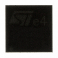
TS4962IQT STMicroelectronics, TS4962IQT Datasheet - Page 31

TS4962IQT
Manufacturer Part Number
TS4962IQT
Description
IC AMP AUDIO PWR 2.8W MONO 8DFN
Manufacturer
STMicroelectronics
Type
Class Dr
Datasheet
1.TS4962IQT.pdf
(44 pages)
Specifications of TS4962IQT
Output Type
1-Channel (Mono)
Max Output Power X Channels @ Load
2.8W x 1 @ 4 Ohm
Voltage - Supply
2.4 V ~ 5.5 V
Features
Depop, Differential Inputs, Standby, Thermal Protection
Mounting Type
Surface Mount
Package / Case
8-DFN
Product
Class-D
Output Power
2 W
Available Set Gain
6 dB
Common Mode Rejection Ratio (min)
57 dB
Thd Plus Noise
1 %
Operating Supply Voltage
3 V, 5 V
Supply Current
2.3 mA
Maximum Operating Temperature
+ 85 C
Mounting Style
SMD/SMT
Audio Load Resistance
8 Ohms
Input Signal Type
Differential
Minimum Operating Temperature
- 40 C
Output Signal Type
Differential
Supply Type
Single
Supply Voltage (max)
5.5 V
Supply Voltage (min)
2.5 V
For Use With
497-6265 - BOARD EVAL FOR TS4962MEIJT
Lead Free Status / RoHS Status
Lead free / RoHS Compliant
Other names
497-5993-2
Available stocks
Company
Part Number
Manufacturer
Quantity
Price
Company:
Part Number:
TS4962IQT
Manufacturer:
TOSHIBA
Quantity:
7 600
Part Number:
TS4962IQT
Manufacturer:
ST
Quantity:
20 000
TS4962
4.3
4.4
Common-mode feedback loop limitations
As explained previously, the common-mode feedback loop allows the output DC bias
voltage to be averaged at V
However, due to a V
page
range depends upon the values of V
V
with
And the result of the calculation must be in the range:
Due to the +/-9% tolerance on the 150 kΩ resistor, it is also important to check V
conditions.
If the result of the V
must be used. With V
For example:
With V
3 V-0.8 V = 2.2 V. With 136.5 kΩ we find 1.97 V and with 163.5 kΩ we have 2.02 V.
Therefore, no input coupling capacitors are required.
Low frequency response
If a low frequency bandwidth limitation is requested, it is possible to use input coupling
capacitors.
In the low frequency region, C
with R
So, for a desired cut-off frequency we can calculate C
with R
icm
value, we can apply this formula (no tolerance on R
4), the common-mode feedback loop can play its role only within a defined range. This
in
in
CC
, a first order high-pass filter with a -3 dB cut-off frequency.
in Ω and F
= 3 V, R
V
---------------------------------------------------------------------------------- - V
CC
×
in
2
CL
R
icm
= 150 k and V
×
icm
in
CC
in Hz.
(
R
+
calculation is not in the previous range, input coupling capacitors
limitation in the input stage (see
in
2
between 2.4 and 2.5 V, input coupling capacitors are mandatory.
V
×
+
icm
CC
136.5kΩ
V
IC
in
/2 for any DC common-mode bias input voltage.
=
Doc ID 10968 Rev 8
(input coupling capacitor) starts to have an effect. C
×
F
V
----------------------------------------------------------------------------- -
C
CL
IC
CC
136.5kΩ
in
0.5V V
)
V
= 2.5 V, we typically find V
CC
=
=
×
IC
2
------------------------------------- -
2π
--------------------------------------- -
2π
R
×
≤
and R
=
in
(
×
×
R
+
icm
≤
In
---------------------
R
R
in
2
+
1
in
1
in
icm
+
≤
×
2
in
+
×
×
V
150kΩ
V
In
(A
CC
≤
C
IC
F
-
Vdiff
V
---------------------------------------------------------------------------------- -
CL
in
×
–
CC
(V)
0.8V
150kΩ
)
). To have a good estimation of the
in
×
2
,
(Hz)
Table 3: Operating conditions on
R
in
(F)
×
):
in
(
R
+
in
2
icm
×
+
(V)
163.5kΩ
V
= 2 V, which is lower than
Application information
IC
×
163.5kΩ
)
icm
in
in these
forms,
31/44


