SC16C2550IB48,128 NXP Semiconductors, SC16C2550IB48,128 Datasheet - Page 42
SC16C2550IB48,128
Manufacturer Part Number
SC16C2550IB48,128
Description
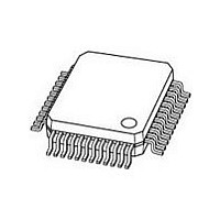
IC DUART SOT313-2
Manufacturer
NXP Semiconductors
Datasheet
1.SC16C2550IN40112.pdf
(46 pages)
Specifications of SC16C2550IB48,128
Features
2 Channels
Number Of Channels
2, DUART
Fifo's
16 Byte
Voltage - Supply
3.5 V ~ 4.5 V
With Auto Flow Control
Yes
With Irda Encoder/decoder
Yes
With False Start Bit Detection
Yes
With Modem Control
Yes
With Cmos
Yes
Mounting Type
Surface Mount
Package / Case
48-LQFP
Transmit Fifo
16Byte
Receive Fifo
16Byte
Transmitter And Receiver Fifo Counter
Yes
Data Rate
5Mbps
Package Type
LQFP
Operating Supply Voltage (max)
5.5V
Mounting
Surface Mount
Pin Count
48
Operating Temperature (min)
-40C
Operating Temperature (max)
85C
Operating Temperature Classification
Industrial
Lead Free Status / RoHS Status
Lead free / RoHS Compliant
Other names
935270020128
SC16C2550IB48-T
SC16C2550IB48-T
SC16C2550IB48-T
SC16C2550IB48-T


Philips Semiconductors
12. Soldering
9397 750 11621
Product data
12.2.1 Soldering by dipping or by solder wave
12.2.2 Manual soldering
12.3.1 Reflow soldering
12.1 Introduction
12.2 Through-hole mount packages
12.3 Surface mount packages
This text gives a very brief insight to a complex technology. A more in-depth account
of soldering ICs can be found in our Data Handbook IC26; Integrated Circuit
Packages (document order number 9398 652 90011).
There is no soldering method that is ideal for all IC packages. Wave soldering is often
preferred when through-hole and surface mount components are mixed on one
printed-circuit board. Wave soldering can still be used for certain surface mount ICs,
but it is not suitable for fine pitch SMDs. In these situations reflow soldering is
recommended. Driven by legislation and environmental forces the worldwide use of
lead-free solder pastes is increasing.
Typical dwell time of the leads in the wave ranges from 3 to 4 seconds at 250 C or
265 C, depending on solder material applied, SnPb or Pb-free respectively.
The total contact time of successive solder waves must not exceed 5 seconds.
The device may be mounted up to the seating plane, but the temperature of the
plastic body must not exceed the specified maximum storage temperature (T
If the printed-circuit board has been pre-heated, forced cooling may be necessary
immediately after soldering to keep the temperature within the permissible limit.
Apply the soldering iron (24 V or less) to the lead(s) of the package, either below the
seating plane or not more than 2 mm above it. If the temperature of the soldering iron
bit is less than 300 C it may remain in contact for up to 10 seconds. If the bit
temperature is between 300 and 400 C, contact may be up to 5 seconds.
Reflow soldering requires solder paste (a suspension of fine solder particles, flux and
binding agent) to be applied to the printed-circuit board by screen printing, stencilling
or pressure-syringe dispensing before package placement.
Several methods exist for reflowing; for example, convection or convection/infrared
heating in a conveyor type oven. Throughput times (preheating, soldering and
cooling) vary between 100 and 200 seconds depending on heating method.
Typical reflow peak temperatures range from 215 to 270 C depending on solder
paste material. The top-surface temperature of the packages should preferably be
kept:
•
below 220 C (SnPb process) or below 245 C (Pb-free process)
– for all the BGA and SSOP-T packages
Dual UART with 16 bytes of transmit and receive FIFOs and IrDA
Rev. 03 — 19 June 2003
© Koninklijke Philips Electronics N.V. 2003. All rights reserved.
SC16C2550
encoder/decoder
stg(max)
42 of 46
).
Related parts for SC16C2550IB48,128
Image
Part Number
Description
Manufacturer
Datasheet
Request
R

Part Number:
Description:
Sc16c2550 Dual Uart With 16 Bytes Of Transmit And Receive Fifos And Infrared Irda Encoder/decoder
Manufacturer:
NXP Semiconductors
Datasheet:
Part Number:
Description:
NXP Semiconductors designed the LPC2420/2460 microcontroller around a 16-bit/32-bitARM7TDMI-S CPU core with real-time debug interfaces that include both JTAG andembedded trace
Manufacturer:
NXP Semiconductors
Datasheet:

Part Number:
Description:
NXP Semiconductors designed the LPC2458 microcontroller around a 16-bit/32-bitARM7TDMI-S CPU core with real-time debug interfaces that include both JTAG andembedded trace
Manufacturer:
NXP Semiconductors
Datasheet:
Part Number:
Description:
NXP Semiconductors designed the LPC2468 microcontroller around a 16-bit/32-bitARM7TDMI-S CPU core with real-time debug interfaces that include both JTAG andembedded trace
Manufacturer:
NXP Semiconductors
Datasheet:
Part Number:
Description:
NXP Semiconductors designed the LPC2470 microcontroller, powered by theARM7TDMI-S core, to be a highly integrated microcontroller for a wide range ofapplications that require advanced communications and high quality graphic displays
Manufacturer:
NXP Semiconductors
Datasheet:
Part Number:
Description:
NXP Semiconductors designed the LPC2478 microcontroller, powered by theARM7TDMI-S core, to be a highly integrated microcontroller for a wide range ofapplications that require advanced communications and high quality graphic displays
Manufacturer:
NXP Semiconductors
Datasheet:
Part Number:
Description:
The Philips Semiconductors XA (eXtended Architecture) family of 16-bit single-chip microcontrollers is powerful enough to easily handle the requirements of high performance embedded applications, yet inexpensive enough to compete in the market for hi
Manufacturer:
NXP Semiconductors
Datasheet:
Part Number:
Description:
The XA-S3 device is a member of Philips Semiconductors? XA(eXtended Architecture) family of high performance 16-bitsingle-chip microcontrollers
Manufacturer:
NXP Semiconductors
Datasheet:

Part Number:
Description:
The NXP BlueStreak LH75401/LH75411 family consists of two low-cost 16/32-bit System-on-Chip (SoC) devices
Manufacturer:
NXP Semiconductors
Datasheet:
Part Number:
Description:
The NXP LPC3130/3131 combine an 180 MHz ARM926EJ-S CPU core, high-speed USB2
Manufacturer:
NXP Semiconductors
Datasheet:
Part Number:
Description:
The NXP LPC3141 combine a 270 MHz ARM926EJ-S CPU core, High-speed USB 2
Manufacturer:
NXP Semiconductors
Part Number:
Description:
The NXP LPC3143 combine a 270 MHz ARM926EJ-S CPU core, High-speed USB 2
Manufacturer:
NXP Semiconductors

Part Number:
Description:
The NXP LPC3152 combines an 180 MHz ARM926EJ-S CPU core, High-speed USB 2
Manufacturer:
NXP Semiconductors
Part Number:
Description:
The NXP LPC3154 combines an 180 MHz ARM926EJ-S CPU core, High-speed USB 2
Manufacturer:
NXP Semiconductors