IS82C52 Intersil, IS82C52 Datasheet - Page 12
IS82C52
Manufacturer Part Number
IS82C52
Description
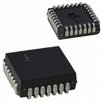
IC PERIPH UART/BRG 16MHZ 28-PLCC
Manufacturer
Intersil
Datasheet
1.IS82C52Z.pdf
(20 pages)
Specifications of IS82C52
Features
Single Chip UART/BRG
Number Of Channels
1, UART
Protocol
RS232C
Voltage - Supply
4.5 V ~ 5.5 V
With Parallel Port
Yes
With False Start Bit Detection
Yes
With Modem Control
Yes
With Cmos
Yes
Mounting Type
Surface Mount
Package / Case
28-LCC (J-Lead)
Peak Reflow Compatible (260 C)
No
Leaded Process Compatible
No
Function
UART/BRG
Rohs Compliant
No
Lead Free Status / RoHS Status
Contains lead / RoHS non-compliant
Available stocks
Company
Part Number
Manufacturer
Quantity
Price
Company:

Part Number:
IS82C52
Manufacturer:
Intersil
Quantity:
60
Company:
Part Number:
IS82C52AZ
Manufacturer:
INTERLS
Quantity:
5 510
Company:
Part Number:
IS82C52AZ
Manufacturer:
ST
Quantity:
5 510


AC Testing Input, Output Waveforms
AC TESTING: All input signals (except IX and RST) must switch between V
AC Electrical Specifications
Timing Requirements and Responses
V
V
(10)
(12)
(13)
(14)
(11)
IL
(1)
(2)
(3)
(4)
(5)
(6)
(7)
(8)
(9)
IH
INPUT
- 0.4V
+ 0.4V
SYMBOL
TCTLCTH
TCTHCTL
TCTHSX
TSVCTL
TDVWH
TWHDX
TRLDV
TRHDZ
TCHCL
TCLCH
TR/TF
TRCO
TFCO
FC
1.5V
FIGURE 12. PROPAGATION DELAY
Select Setup to Control Leading Edge
Select Hold from Control Trailing Edge
Control Pulse Width
Control Disable to Control Enable
Read Low to Data Valid
Read Disable
Data Setup Time
Data Hold Time
Clock Frequency
Clock High Time
Clock Low Time
IX Input Rise/Fall Time (External Clock)
Clock Output Fall Time
Clock Output Rise Time
12
V
CC
PARAMETER
= 5.0V ±10%, T
1.5V
T
OUTPUT
A
A
V
V
= -55°C to +125°C (M82C52)
OL
= 0°C to +70°C (C82C52), T
OH
82C52
82C52
IL
-0.4V and V
MIN
150
190
30
50
50
20
25
25
0
0
-
-
-
-
A
OUTPUT
IH
= -40°C to +85°C (l82C52)
FIGURE 13. ENABLE/DISABLE DELAY
+0.4V. Input rise and fall times are driven at 1ns/V.
MAX
120
60
16
15
15
tx
-
-
-
-
-
-
-
-
UNITS
MHz
ns
ns
ns
ns
ns
ns
ns
ns
ns
ns
ns
ns
ns
90%
10%
Control Consists of RD or
WR
1, See AC Test Circuit
2, See AC Test Circuit
TCHCL + TCLCH must be
≥ 62.5ns
Whichever is smaller
CL = 50pf
CL = 50pf
tx
≥
TEST CONDITIONS
----------- - or 50ns
6FC
1
April 26, 2006
FN2950.3
Related parts for IS82C52
Image
Part Number
Description
Manufacturer
Datasheet
Request
R

Part Number:
Description:
Intersil Corporation [CMOS Serial Controller Interface]
Manufacturer:
Intersil Corporation
Datasheet:
Part Number:
Description:
Manufacturer:
Intersil Corporation
Datasheet:
Part Number:
Description:
357-036-542-201 CARDEDGE 36POS DL .156 BLK LOPRO
Manufacturer:
Intersil Corporation
Datasheet:
Part Number:
Description:
1024-Word x 4-Bit LSI Static RAM
Manufacturer:
Intersil Corporation
Datasheet:
Part Number:
Description:
General Purpose NPN Transistor Arrays FN341.4
Manufacturer:
Intersil Corporation
Datasheet:
Part Number:
Description:
CMOS 16-Bit Microprocessor
Manufacturer:
Intersil Corporation
Datasheet:
Part Number:
Description:
Manufacturer:
Intersil Corporation
Datasheet:
Part Number:
Description:
Manufacturer:
Intersil Corporation
Datasheet:
Part Number:
Description:
Manufacturer:
Intersil Corporation
Datasheet:
Part Number:
Description:
Manufacturer:
Intersil Corporation
Datasheet:
Part Number:
Description:
CMOS 6-Bit Latch and Decoder Memory Interfaces
Manufacturer:
Intersil Corporation
Datasheet:
Part Number:
Description:
CA3046General Purpose NPN Transistor Arrays
Manufacturer:
Intersil Corporation
Datasheet:
Part Number:
Description:
Manufacturer:
Intersil Corporation
Datasheet:
Part Number:
Description:
TR909 DLC/FLC SLIC with Low Power Standby
Manufacturer:
Intersil Corporation
Datasheet:
Part Number:
Description:
Manufacturer:
Intersil Corporation
Datasheet: