SC16C554BIBS,528 NXP Semiconductors, SC16C554BIBS,528 Datasheet - Page 22
SC16C554BIBS,528
Manufacturer Part Number
SC16C554BIBS,528
Description
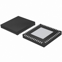
IC UART QUAD SOT778-3
Manufacturer
NXP Semiconductors
Datasheet
1.SC16C554BIB80528.pdf
(58 pages)
Specifications of SC16C554BIBS,528
Number Of Channels
4, QUART
Fifo's
16 Byte
Voltage - Supply
2.5V, 3.3V, 5V
With Auto Flow Control
Yes
With False Start Bit Detection
Yes
With Modem Control
Yes
With Cmos
Yes
Mounting Type
Surface Mount
Package / Case
48-VQFN Exposed Pad, 48-HVQFN, 48-SQFN, 48-DHVQFN
Lead Free Status / RoHS Status
Lead free / RoHS Compliant
Other names
935279072528
SC16C554BIBS-F
SC16C554BIBS-F
SC16C554BIBS-F
SC16C554BIBS-F


NXP Semiconductors
SC16C554B_554DB
Product data sheet
6.7 DMA operation
6.8 Loopback mode
The SC16C554B/554DB FIFO trigger level provides additional flexibility to the user for
block mode operation. LSR[6:5] provide an indication when the transmitter is empty or has
an empty location(s). The user can optionally operate the transmit and receive FIFOs in
the DMA mode (FCR[3]). When the transmit and receive FIFOs are enabled and the DMA
mode is de-activated (DMA Mode 0), the SC16C554B/554DB activates the interrupt
output pin for each data transmit or receive operation. When DMA mode is activated
(DMA Mode 1), the user takes the advantage of block mode operation by loading or
unloading the FIFO in a block sequence determined by the preset trigger level. In this
mode, the SC16C554B/554DB sets the interrupt output pin when the characters in the
receive FIFOs are above the receive trigger level.
Remark: DMA operation is not supported in the HVQFN48 package.
The internal loopback capability allows on-board diagnostics. In the Loopback mode, the
normal modem interface pins are disconnected and reconfigured for loopback internally.
MCR[3:0] register bits are used for controlling loopback diagnostic testing. In the
Loopback mode, OP2 and OP1 in the MCR register (bits 3:2) control the modem RI and
CD inputs, respectively. MCR signals RTS and DTR (bits 1:0) are used to control the
modem CTS and DSR inputs, respectively. The transmitter output (TX) and the receiver
input (RX) are disconnected from their associated interface pins, and instead are
connected together internally (see
disconnected from their normal modem control input pins, and instead are connected
internally to RTS, DTR, OP2 and OP1. Loopback test data is entered into the Transmit
Holding Register via the user data bus interface, D0 to D7. The transmit UART serializes
the data and passes the serial data to the receive UART via the internal loopback
connection. The receive UART converts the serial data back into parallel data that is then
made available at the user data interface D0 to D7. The user optionally compares the
received data to the initial transmitted data for verifying error-free operation of the UART
TX/RX circuits.
In this mode, the receiver and transmitter interrupts are fully operational. The Modem
Control Interrupts are also operational. However, the interrupts can only be read using
lower four bits of the Modem Status Register (MSR[3:0]) instead of the four Modem Status
Register bits 7:4. The interrupts are still controlled by the IER.
All information provided in this document is subject to legal disclaimers.
5 V, 3.3 V and 2.5 V quad UART, 5 Mbit/s (max.) with 16-byte FIFOs
Rev. 4 — 8 June 2010
Figure
14). The CTS, DSR, CD, and RI are
SC16C554B/554DB
© NXP B.V. 2010. All rights reserved.
22 of 58
Related parts for SC16C554BIBS,528
Image
Part Number
Description
Manufacturer
Datasheet
Request
R

Part Number:
Description:
NXP Semiconductors designed the LPC2420/2460 microcontroller around a 16-bit/32-bitARM7TDMI-S CPU core with real-time debug interfaces that include both JTAG andembedded trace
Manufacturer:
NXP Semiconductors
Datasheet:

Part Number:
Description:
NXP Semiconductors designed the LPC2458 microcontroller around a 16-bit/32-bitARM7TDMI-S CPU core with real-time debug interfaces that include both JTAG andembedded trace
Manufacturer:
NXP Semiconductors
Datasheet:
Part Number:
Description:
NXP Semiconductors designed the LPC2468 microcontroller around a 16-bit/32-bitARM7TDMI-S CPU core with real-time debug interfaces that include both JTAG andembedded trace
Manufacturer:
NXP Semiconductors
Datasheet:
Part Number:
Description:
NXP Semiconductors designed the LPC2470 microcontroller, powered by theARM7TDMI-S core, to be a highly integrated microcontroller for a wide range ofapplications that require advanced communications and high quality graphic displays
Manufacturer:
NXP Semiconductors
Datasheet:
Part Number:
Description:
NXP Semiconductors designed the LPC2478 microcontroller, powered by theARM7TDMI-S core, to be a highly integrated microcontroller for a wide range ofapplications that require advanced communications and high quality graphic displays
Manufacturer:
NXP Semiconductors
Datasheet:
Part Number:
Description:
The Philips Semiconductors XA (eXtended Architecture) family of 16-bit single-chip microcontrollers is powerful enough to easily handle the requirements of high performance embedded applications, yet inexpensive enough to compete in the market for hi
Manufacturer:
NXP Semiconductors
Datasheet:
Part Number:
Description:
The XA-S3 device is a member of Philips Semiconductors? XA(eXtended Architecture) family of high performance 16-bitsingle-chip microcontrollers
Manufacturer:
NXP Semiconductors
Datasheet:

Part Number:
Description:
The NXP BlueStreak LH75401/LH75411 family consists of two low-cost 16/32-bit System-on-Chip (SoC) devices
Manufacturer:
NXP Semiconductors
Datasheet:
Part Number:
Description:
The NXP LPC3130/3131 combine an 180 MHz ARM926EJ-S CPU core, high-speed USB2
Manufacturer:
NXP Semiconductors
Datasheet:
Part Number:
Description:
The NXP LPC3141 combine a 270 MHz ARM926EJ-S CPU core, High-speed USB 2
Manufacturer:
NXP Semiconductors
Part Number:
Description:
The NXP LPC3143 combine a 270 MHz ARM926EJ-S CPU core, High-speed USB 2
Manufacturer:
NXP Semiconductors

Part Number:
Description:
The NXP LPC3152 combines an 180 MHz ARM926EJ-S CPU core, High-speed USB 2
Manufacturer:
NXP Semiconductors
Part Number:
Description:
The NXP LPC3154 combines an 180 MHz ARM926EJ-S CPU core, High-speed USB 2
Manufacturer:
NXP Semiconductors

Part Number:
Description:
Standard level N-channel enhancement mode Field-Effect Transistor (FET) in a plastic package using NXP High-Performance Automotive (HPA) TrenchMOS technology
Manufacturer:
NXP Semiconductors
Datasheet: