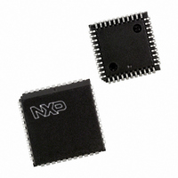
SC28L91A1A,518 NXP Semiconductors, SC28L91A1A,518 Datasheet - Page 25

SC28L91A1A,518
Manufacturer Part Number
SC28L91A1A,518
Description
IC UART SOT187-2
Manufacturer
NXP Semiconductors
Series
IMPACTr
Datasheet
1.SC28L91A1A529.pdf
(43 pages)
Specifications of SC28L91A1A,518
Features
False-start Bit Detection
Number Of Channels
1, UART
Fifo's
16 Byte
Voltage - Supply
3.3V, 5V
With Auto Flow Control
Yes
With False Start Bit Detection
Yes
With Modem Control
Yes
With Cmos
Yes
Mounting Type
Surface Mount
Package / Case
44-LCC (J-Lead)
Lead Free Status / RoHS Status
Lead free / RoHS Compliant
Other names
935267418518
SC28L91A1A-T
SC28L91A1A-T
SC28L91A1A-T
SC28L91A1A-T
Available stocks
Company
Part Number
Manufacturer
Quantity
Price
Company:
Part Number:
SC28L91A1A,518
Manufacturer:
NXP Semiconductors
Quantity:
10 000
If this bit is 0, CTSN has no effect on the transmitter. If this bit is a 1,
Philips Semiconductors
6. The last character will be transmitted and OPR[0] will be reset
MR2[4]— Clear-to-Send Control
the transmitter checks the state of CTSN (IP0) the time it is ready to
send a character. If IP0 is asserted (Low), the character is
transmitted. If it is negated (High), the TxD output remains in the
marking state and the transmission is delayed until CTSN goes low.
Changes in CTSN while a character is being transmitted do not
affect the transmission of that character..
2004 Oct 21
3.3 V or 5.0 V Universal Asynchronous
Receiver/Transmitter (UART)
one bit time after the last stop bit, causing RTSN to be negated.
25
MR2[3:0]— Stop Bit Length Select
This field programs the length of the stop bit appended to the
transmitted character. Stop bit lengths of 9/16 to 1 and 1–9/16 to 2
bits, in increments of 1/16 bit, can be programmed for character
lengths of 6, 7, and 8 bits. For a character lengths of 5 bits, 1–1/16
to 2 stop bits can be programmed in increments of 1/16 bit. In all
cases, the receiver only checks for a ‘mark’ condition at the center
of the stop bit position (one half-bit time after the last data bit, or
after the parity bit if enabled is sampled).
If an external 1X clock is used for the transmitter, then MR2[3] = 0
selects one stop bit and MR2[3] = 1 selects two stop bits to be
transmitted.
SC28L91
Product data sheet


