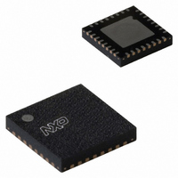
SC16C752BIBS,151 NXP Semiconductors, SC16C752BIBS,151 Datasheet - Page 13

SC16C752BIBS,151
Manufacturer Part Number
SC16C752BIBS,151
Description
IC UART DUAL W/FIFO 32-HVQFN
Manufacturer
NXP Semiconductors
Type
Dual UART with 64-byte FIFOsr
Datasheet
1.SC16C752BIBS151.pdf
(47 pages)
Specifications of SC16C752BIBS,151
Number Of Channels
2, DUART
Package / Case
32-VFQFN Exposed Pad
Features
False-start Bit Detection
Fifo's
64 Byte
Voltage - Supply
2.5V, 3.3V, 5V
With Auto Flow Control
Yes
With False Start Bit Detection
Yes
With Modem Control
Yes
Mounting Type
Surface Mount
Data Rate
5 Mbps
Supply Voltage (max)
5.5 V
Supply Voltage (min)
2.25 V
Supply Current
4.5 mA
Maximum Operating Temperature
+ 85 C
Minimum Operating Temperature
- 40 C
Mounting Style
SMD/SMT
Operating Supply Voltage
2.5 V or 3.3 V or 5 V
Lead Free Status / RoHS Status
Lead free / RoHS Compliant
Lead Free Status / RoHS Status
Lead free / RoHS Compliant, Lead free / RoHS Compliant
Other names
568-3288
935276389151
SC16C752BIBS-S
935276389151
SC16C752BIBS-S
NXP Semiconductors
Table 6.
SC16C752B
Product data sheet
IIR[5:0]
00 0001
00 0110
00 1100
00 0100
00 0010
00 0000
01 0000
10 0000
Interrupt control functions
Priority
level
None
1
2
2
3
4
5
6
6.5 Interrupts
The SC16C752B has interrupt generation and prioritization (six prioritized levels of
interrupts) capability. The Interrupt Enable Register (IER) enables each of the six types of
interrupts and the INTA/INTB signal in response to an interrupt generation. The IER can
also disable the interrupt system by clearing bit 0 to bit 3 and bit 5 to bit 7. When an
interrupt is generated, the IIR indicates that an interrupt is pending and provides the type
of interrupt through IIR[5:0].
It is important to note that for the framing error, parity error, and break conditions, LSR[7]
generates the interrupt. LSR[7] is set when there is an error anywhere in the RX FIFO,
and is cleared only when there are no more errors remaining in the FIFO. LSR[4:2] always
represent the error status for the received character at the top of the RX FIFO. Reading
the RX FIFO updates LSR[4:2] to the appropriate status for the new character at the top of
the FIFO. If the RX FIFO is empty, then LSR[4:2] are all zeros.
For the Xoff interrupt, if an Xoff flow character detection caused the interrupt, the interrupt
is cleared by an Xon flow character detection. If a special character detection caused the
interrupt, the interrupt is cleared by a read of the LSR.
Interrupt type
none
receiver line status
RX time-out
RHR interrupt
THR interrupt
modem status
Xoff interrupt
CTS, RTS
All information provided in this document is subject to legal disclaimers.
5 V, 2.2 V and 2.5 V dual UART, 5 Mbit/s (max.), with 64-byte FIFOs
Interrupt source
none
OE, FE, PE, or BI errors occur in
characters in the RX FIFO
stale data in RX FIFO
DRDY (data ready)
(FIFO disable)
RX FIFO above trigger level
(FIFO enable)
TFE (THR empty)
(FIFO disable)
TX FIFO passes above trigger level
(FIFO enable)
MSR[3:0] = logic 0
receive Xoff character(s)/special
character
RTSn pin or CTSn pin change state
from active (LOW) to inactive (HIGH)
Rev. 6 — 30 November 2010
Table 6
summarizes the interrupt control functions.
Interrupt reset method
none
FE, PE, BI: all erroneous
characters are read from the
RX FIFO.
OE: read LSR
read RHR
read RHR
read IIR or a write to the THR
read MSR
receive Xon character(s)/Read of
IIR
read IIR
SC16C752B
© NXP B.V. 2010. All rights reserved.
13 of 47


