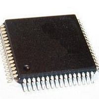
PSB 2132 H V2.2 Infineon Technologies, PSB 2132 H V2.2 Datasheet - Page 53

PSB 2132 H V2.2
Manufacturer Part Number
PSB 2132 H V2.2
Description
IC CODEC FILTER 2CHAN MQFP-64
Manufacturer
Infineon Technologies
Series
SICOFI®r
Datasheet
1.PSB_2132_H_V2.2.pdf
(69 pages)
Specifications of PSB 2132 H V2.2
Package / Case
64-QFP
Function
CODEC Filter
Interface
IOM-2 PCM, SPI
Number Of Circuits
2
Voltage - Supply
5V
Current - Supply
18mA
Power (watts)
90mW
Mounting Type
Surface Mount
Includes
Level Metering Function, Tone Generation
Number Of Adc Inputs
2
Number Of Dac Outputs
2
Interface Type
Serial
Operating Supply Voltage
5 V
Maximum Operating Temperature
+ 70 C
Mounting Style
SMD/SMT
Minimum Operating Temperature
0 C
Number Of Channels
2
Snr
35.4 dB
Supply Current
40 mA
Lead Free Status / RoHS Status
Lead free / RoHS Compliant
Operating Temperature
-
Lead Free Status / RoHS Status
Lead free / RoHS Compliant, Lead free / RoHS Compliant
Other names
PSB2132HV2.2XT
SP000007696
SP000007696
8.4
V
8.4.1
Coupling capacitors are required on pins V
The recommended value for V
depends on the input impedance of the SLIC (see Figure 14 in Chapter 5.1).
8.5
To reset the SICOFI
be below 1.2 V (TTL-Schmitt-Trigger Input) and must persist longer than 3 µs.
Note: Spikes shorter than 1 µs will be ignored.
Hardware Reference Manual
Input resistance
Output resistance
Output load
Input leakage current
Input offset voltage
Output offset voltage
Input voltage range (AC)
DD
= 5 V 5%; GNDD = 0 V; GNDA = 0 V;
Parameter
Analog Interface
Coupling Capacitors at the Analog Interface
Reset Timing
®
2-TE to Reset State, logic low pulses applied to pin RESET# must
Symbol
V
V
V
R
C
R
R
I
IN
OO
IL
IO
IN
O
L
L
i
is >39 nF. The required value for the V
Electrical Characteristics and Timing Diagrams
min.
160
300
Limit Values
IN
44
T
and V
A
typ.
270
= 0 °C to +70 °C
0.1
OUT
max.
.
0.25
2.223
380
50
1.0
50
50
Unit
mV
mV
kW
µA
pF
V
0
Test Condition
0
V
OUT
IN
V
PSB 2132
IN
2001-02-20
V
capacitor
DD
V
DD


