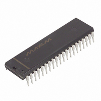
DS2180A+ Maxim Integrated Products, DS2180A+ Datasheet - Page 28

DS2180A+
Manufacturer Part Number
DS2180A+
Description
IC TRANSCEIVER T1 40-DIP
Manufacturer
Maxim Integrated Products
Datasheet
1.DS2180A.pdf
(35 pages)
Specifications of DS2180A+
Function
Transceiver
Interface
T1
Number Of Circuits
1
Voltage - Supply
4.5 V ~ 5.5 V
Current - Supply
3mA
Operating Temperature
0°C ~ 70°C
Mounting Type
Through Hole
Package / Case
40-DIP (0.600", 15.24mm)
Includes
Alarm Generation and Detection, B7 Stuffing Mode, B8ZS Mode, Error Detection and Counter, "Hardware" Mode, Transparent Mode
Product
Framer
Number Of Transceivers
1
Supply Voltage (max)
5.5 V
Supply Voltage (min)
4.5 V
Supply Current (max)
10 mA
Maximum Operating Temperature
+ 70 C
Minimum Operating Temperature
0 C
Mounting Style
Through Hole
Lead Free Status / RoHS Status
Lead free / RoHS Compliant
Power (watts)
-
Lead Free Status / Rohs Status
Lead free / RoHS Compliant
DS2180A
PROCESSOR-BASED TRANSMIT SIGNALING INSERTION Figure 23
PROCESSOR-BASED SIGNALING
Many robbed-bit signaling applications utilize a microprocessor to insert transmit signaling data into the
out-going data stream. The circuit shown in Figure 23 “decouples” the processor timing from that of the
DS2180A by use of a small FIFO memory. The processor writes to the FIFO (6 bytes are written: 3 for A
data, 3 for B data) only when signaling updates are required. The system is interrupt-driven from the
transmit multiframe sync input; the processor must update the FIFO prior to Frame 6 (625 s after
interrupt) to prevent data corruption. The application circuit shown supports 193S framing. Additional
hardware is required for 193E applications.
28 of 35


