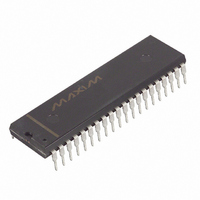
DS2180A+ Maxim Integrated Products, DS2180A+ Datasheet - Page 24

DS2180A+
Manufacturer Part Number
DS2180A+
Description
IC TRANSCEIVER T1 40-DIP
Manufacturer
Maxim Integrated Products
Datasheet
1.DS2180A.pdf
(35 pages)
Specifications of DS2180A+
Function
Transceiver
Interface
T1
Number Of Circuits
1
Voltage - Supply
4.5 V ~ 5.5 V
Current - Supply
3mA
Operating Temperature
0°C ~ 70°C
Mounting Type
Through Hole
Package / Case
40-DIP (0.600", 15.24mm)
Includes
Alarm Generation and Detection, B7 Stuffing Mode, B8ZS Mode, Error Detection and Counter, "Hardware" Mode, Transparent Mode
Product
Framer
Number Of Transceivers
1
Supply Voltage (max)
5.5 V
Supply Voltage (min)
4.5 V
Supply Current (max)
10 mA
Maximum Operating Temperature
+ 70 C
Minimum Operating Temperature
0 C
Mounting Style
Through Hole
Lead Free Status / RoHS Status
Lead free / RoHS Compliant
Power (watts)
-
Lead Free Status / Rohs Status
Lead free / RoHS Compliant
193E FRAMING FORMAT Table 7
NOTES:
1. FPS – Framing Pattern Sequence.
2. FDL – 4 kHz Facility Data Link; M = message bits.
3. CRC – Cyclic Redundancy Check bits. The CRC code will be internally generated by the device
4. The user may program any individual channels clear, in which case bit 8 will be used for data, not
5. Depending on application, the user can support 2-state, 4-state or 16-state signaling by the appropriate
NUMBER
FRAME
when TCR.5=0. When TCR.5=1, externally supplied CRC data will be sampled at TSER during the
F-bit time of frames 2, 6, 10, 14, 18, 22.
signaling.
decodes of TMO, TSIGFR, TSIGSEL (Transmit Side) and RMSYNC, RSIGFR and RSIGSEL
(Receive Side).
10
11
12
13
14
15
16
17
18
19
20
21
22
23
24
1
2
3
4
5
6
7
8
9
FPS
0
0
1
0
1
1
-
-
-
-
-
-
-
-
-
-
-
-
-
-
-
-
-
-
1
F-BIT USE
FPL
M
M
M
M
M
M
M
M
M
M
M
M
-
-
-
-
-
-
-
-
-
-
-
-
2
CRC
C1
C2
C3
C4
C5
C6
-
-
-
-
-
-
-
-
-
-
-
-
-
-
-
-
-
-
3
BIT USE IN EACH CHANNEL
BITS 1-8
BITS 1-8
BITS 1-8
BITS 1-8
BITS 1-8
BITS 1-7
BITS 1-8
BITS 1-8
BITS 1-8
BITS 1-8
BITS 1-8
BITS 1-7
BITS 1-8
BITS 1-8
BITS 1-8
BITS 1-8
BITS 1-8
BITS 1-7
BITS 1-8
BITS 1-8
BITS 1-8
BITS 1-8
BITS 1-8
BITS 1-7
DATA
24 of 35
SIGNALING
BIT 8
BIT 8
BIT 8
BIT 8
STATE
A
A
A
A
2
SIGNALING-BIT USE
STATE
A
B
C
B
4
DS2180A
STATE
16
A
B
C
D


