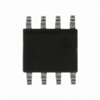
CPC5710NTR Clare, CPC5710NTR Datasheet - Page 4

CPC5710NTR
Manufacturer Part Number
CPC5710NTR
Description
IC PHONE LINE MONITOR 8-SOIC
Manufacturer
Clare
Series
LITELINK®r
Specifications of CPC5710NTR
Function
Phone Line Monitor (PLM)
Number Of Circuits
1
Voltage - Supply
3 V ~ 5.5 V
Current - Supply
10mA
Power (watts)
300mW
Operating Temperature
-40°C ~ 85°C
Mounting Type
Surface Mount
Package / Case
8-SOIC (3.9mm Width)
Includes
Full-Wave Ring Detector
Lead Free Status / RoHS Status
Lead free / RoHS Compliant
Interface
-
Other names
CLA301TR
CPC5710NTR
CPC5710NTR
Available stocks
Company
Part Number
Manufacturer
Quantity
Price
Part Number:
CPC5710NTR
Manufacturer:
CLARE
Quantity:
20 000
CPC2400E
4
Functional Description
The CPC2400E is a small, full featured, 2400 baud
module intended for embedded applications and is fully
FCC Part 68 approved. The CPC2400E includes a user
transferable FCC registration number which the end
product must display (see section for more details). The
module consists of a Data Access Arrangement (DAA),
V.22bis data pump, and a microcontroller on a 1.00” x
2.50” PCB.
The CPC2400E connects to the telephone lines TIP and
RING leads and must be made through an approved
RJ-11 jack. The CPC2400E supports the industry stan-
dard AT command set (see AT Command set section for
further details).
The CPC2400E operates off a single +5V supply and
supports low power modes of operation. When the
device is not in use, it automatically enters sleep mode,
reducing supply current to a minimum. An incoming ring
signal from the phone lines powers up the device (wake-
on ring).
An evaluation board is available for testing the
CPC2400E. This evaluation board includes an RS232
line driver, LED status indicators and an amplified speak-
er circuit. When used with the evaluation board, the
CPC2400E also meets the FCC Part 15B emissions test.
Contact Clare for more information on the CPC2400E
Evaluation Board.
DAA
The DAA portion of the CPC2400E has been designed
to interface directly with the U.S. PSTN as governed by
the FCC. The DAA includes the circuitry for hookswitch,
ring detection, gyrator, surge protection and analog sig-
nal coupling transformer. The DAA circuitry provides up
to 1000 V
tries using a PSTN similar to the U.S. (Canada, Japan),
the product using the CPC2400E must be submitted to
a suitable test house for approval. Consult Clare for fur-
ther information.
FCC Part 68: Connecting to the PSTN
1. General
Clare’s CPC2400E complies with FCC Part 68 rules
which regulates equipment connected to the telephone
network. The CPC2400E provides a user transferable
Part 68 registration which means that customers can
use Clare’s registration number for the CPC2400E.
Customers who wish, can reregister the modem under
their name. Reregistration assigns the customer a
unique registration number. No additional FCC Part 68
submittal is required for equipment using Clare’s
CPC2400E module.
RMS
of longitudinal surge protection. For coun-
www.clare.com
2. Repairs
The FCC requires that Clare makes all necessary
repairs to the modem. If you are experiencing problems
with the CPC2400E, contact Clare at 1-800-272-5273
for further information. If repairs are necessary after the
modem has been installed in your product and delivered
to your customer, the modem must be returned to you
where the CPC2400E can be removed and sent back to
Clare.
3. Label Instructions
A label similar to the following should be made visible on
the outside of the end user product.
Complies with Part 68 of FCC Rules
Registration Number:
Ringer Equivalence:
Required Connection:
4. Design Guidelines
The following design guidelines should be followed to
insure compatibility to FCC Part 68 tests:
4.1. The CPC2400E, the RJ-11 jack and the interface
circuitry must be mounted on a PCB the should meet
UL 94V-0 flammability standard.
4.2. Tip and Ring traces from the CPC2400E to the RJ-
11 jack should be isolated by a minimum of 1.5mm
(0.06in) to prevent breakdown. Traces must have a min-
imum width of 0.5mm (.02in).
4.3 Insure that module is securely installed to the host
system. Vibration and drop tests will loosen compo-
nents that are not securely mounted. One of two meth-
ods for securing the module should be used:
4.4. Components used must be able to withstand tem-
perature and humidity extremes per FCC Part 68.
4.3.1 Soldered to the main PCB. This method is well
suited for harsh environments where the end product
may be subjected to shock and vibrationas in indus-
trial environments (equipment monitoring, etc.).
4.3.2 Socketed to the main PCB. This method is well
suited for environments where the end product is not
subjected to shock and vibrations as in consumer
applications (set top boxes, etc.).
RJ-11
LVRPHL-25931-MD-E
0.6B
Rev. 2


