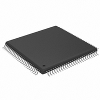
MAX9675ECQ+ Maxim Integrated Products, MAX9675ECQ+ Datasheet

MAX9675ECQ+
Specifications of MAX9675ECQ+
Related parts for MAX9675ECQ+
MAX9675ECQ+ Summary of contents
Page 1
... V ♦ High-Impedance Output Disable for Wired-OR Connections ♦ 0.1dB Gain Flatness to 14MHz ♦ -3dB Bandwidth 110MHz ♦ -62dB Crosstalk, -110dB Isolation at 6MHz PART MAX9675ECQ+ +Denotes a lead-free/RoHS-compliant package. Applications Pin Configuration appears at end of data sheet. MAX9675 IN0 IN1 MONITOR IN2 ...
Page 2
Video Crosspoint Switch with Programmable Gain ABSOLUTE MAXIMUM RATINGS Analog Supply Voltage ( .....................................+11V CC EE Digital Supply Voltage (V - DGND) ...................................+6V DD Analog Supplies to Analog Ground (V - AGND) and ...
Page 3
DC ELECTRICAL CHARACTERISTICS—DUAL SUPPLIES ±5V (continued +5V -5V +5V, AGND = DGND = noted. Typical values are +25°C.) (Note 5) A PARAMETER SYMBOL Temperature Coefficient of ...
Page 4
Video Crosspoint Switch with Programmable Gain LOGIC-LEVEL CHARACTERISTICS (V = +5V -5V +2.7V to +5.5V, AGND = DGND = otherwise noted. Typical values are at T PARAMETER ...
Page 5
AC ELECTRICAL CHARACTERISTICS—DUAL SUPPLIES ±5V (continued +5V -5V +5V, AGND = DGND = wise noted.) PARAMETER SYMBOL Settling Time t S 0.1% Switching Transient (Glitch) (Note 3) AC Power-Supply ...
Page 6
Video Crosspoint Switch with Programmable Gain SWITCHING CHARACTERISTICS (V = +5V -5V +2.7V to +5.5V, DGND = AGND = +1V/V, and ...
Page 7
Symbol Definitions SYMBOL TYPE Ao Signal Ce Signal Ck Signal Di Signal Do Signal Md Signal Oe Signal Rst Signal Ud Signal Vo Signal H Property Hd Property L Property Mn Property Mx Property Pd Property Su Property Tr Property ...
Page 8
Video Crosspoint Switch with Programmable Gain DATA AND CONTROL TIMING Ce SuCe Ck: SCLK t MnHCk t MnLCk Di: DIN Do: DOUT t PdDo t Ud: UPDATE HdUd Hi-Z Vo: OUT_ Ao: AOUT Rst: ...
Page 9
V = -5V +5V, AGND = DGND = noted.) LARGE-SIGNAL FREQUENCY RESPONSE 150Ω +2V +1V/V ...
Page 10
Video Crosspoint Switch with Programmable Gain (V = +5V and V = -5V +5V, AGND = DGND = noted.) LARGE-SIGNAL FREQUENCY RESPONSE (A = +2V/ ...
Page 11
V = -5V +5V, AGND = DGND = noted.) OFF-ISOLATION vs. FREQUENCY -40 -50 -60 -70 -80 -90 -100 -110 -120 100k 1M 10M 100M FREQUENCY (Hz) LARGE-SIGNAL PULSE ...
Page 12
Video Crosspoint Switch with Programmable Gain (V = +5V and V = -5V +5V, AGND = DGND = noted.) SWITCHING TRANSIENT (GLITCH +1V/V) V MAX9675 toc28 V ...
Page 13
V = -5V +5V, AGND = DGND = noted.) GAIN vs. TEMPERATURE 0.20 0.15 0.10 0. +2V -0. +1V/V V -0.10 -0.15 -0.20 ...
Page 14
Video Crosspoint Switch with Programmable Gain PIN NAME 11, 13, 15, IN4–IN15 17, 19, 21 10, 12, 14, 16, 45, 46, 82, 83, 84, 91, AGND ...
Page 15
MAX9675 IN0 IN1 IN2 IN15 POWER-ON RESET RESET DIN SCLK SERIAL UPDATE INTERFACE CE A0–A3 MODE *A = +1V/V OR +2V/V V Detailed Description The MAX9675 is a highly integrated 16 ing video crosspoint switch matrix. All inputs and out- ...
Page 16
Video Crosspoint Switch with Programmable Gain Table 1. Operation Truth Table CE UPDATE SCLK DIN ↓ ↓ ...
Page 17
Table 2. 16-Bit Serial Control Word Bit Assignments (Mode 0: Individual Output Address Mode) BIT NAME 0 LSB of input channel Input Address 0 (LSB) select address 1 Input Address 1 2 Input Address 2 MSB of input channel 3 ...
Page 18
Video Crosspoint Switch with Programmable Gain 16-BIT INDIVIDUAL OUTPUT ADDRESS MODE: FIRST 2 BITS ARE DON'T CARE BITS, LAST 14 BITS CLOCKED INTO DIN WHEN MODE = 0 CREATE ADDRESS WORD; IC ADDRESS A3–A0 IS COMPARED ...
Page 19
SCLK CE MODE SCLK CE MODE DIN Figure 3. Serial Interface Block Diagram Table 6. Input Selection Programming INPUT ADDRESS BIT (MSB) (LSB ...
Page 20
Video Crosspoint Switch with Programmable Gain t MnLCk SCLK t t SuDi HdDi DIN UPDATE t PdDo DOUT SCLK EXAMPLE OF 6-BIT SERIAL CONTROL WORD FOR OUTPUT CONTROL DIN CROSSPOINT = 6-BIT CONTROL ...
Page 21
The MAX9675 features an asynchronous bidirectional RESET with an internal 20kΩ pullup resistor to V When RESET is pulled low, either by internal circuitry, or driven externally, the analog output buffers are latched into a high-impedance state. After RESET is ...
Page 22
Video Crosspoint Switch with Programmable Gain 16 16 MAX9675 IN OUT IN (0–15 MAX9675 IN OUT IN (16–31 MAX9675 IN OUT IN (32–47 MAX9675 IN OUT IN (48–63) OUTPUTS (0–15) ...
Page 23
Driving a PCB Interconnect or a Cable (A = +1V/V or +2V/V) V The MAX9675 output buffers can be programmed to either A = +1V/V or +2V/V. The +1V/V configuration is V typically used when driving a short-length (less than ...
Page 24
Video Crosspoint Switch with Programmable Gain CHIP ADDRESS = 0 DIN DOUT MAX9675 HOST SCLK CONTROLLER CE MODE UPDATE Figure 9. Matrix Mode Programming 24 ______________________________________________________________________________________ CHIP ADDRESS = 1 DIN DOUT MAX9675 A3 SCLK A3 ...
Page 25
TOP VIEW + IN4 1 AGND 2 IN5 3 AGND 4 IN6 5 AGND 6 IN7 7 AGND 8 IN8 9 AGND 10 IN9 11 AGND 12 IN10 13 AGND 14 IN11 15 AGND 16 IN12 IN13 ...
Page 26
Video Crosspoint Switch with Programmable Gain For the latest package outline information and land patterns www.maxim-ic.com/packages. 26 ______________________________________________________________________________________ Package Information PACKAGE OUTLINE 100L TQFP, 14x14x1.0mm 1 21-0085 B 2 ...
Page 27
... Maxim cannot assume responsibility for use of any circuitry other than circuitry entirely embodied in a Maxim product. No circuit patent licenses are implied. Maxim reserves the right to change the circuitry and specifications without notice at any time. Maxim Integrated Products, 120 San Gabriel Drive, Sunnyvale, CA 94086 408-737-7600 ____________________ 27 © 2008 Maxim Integrated Products ...


