RC1005J220CS Samsung Semiconductor, RC1005J220CS Datasheet

RC1005J220CS
Specifications of RC1005J220CS
Related parts for RC1005J220CS
RC1005J220CS Summary of contents
Page 1
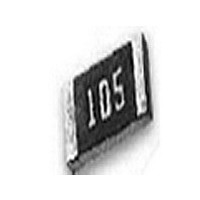
... Thick Film Chip Resistor Chip resistors, which are available for surface mounting, are general passive component which is useful for voltage drop, current controlling in circuit and surface mounting is available. Samsung electro-mechanics also manufactures a wide range of chip resistors such as general, precision, trimmable and low ohms and so on. ...
Page 2
DIMENSION The dimension is expressed digit number base on SI unit (mm). <Table 1> First 2 digits are length of resistor, and last 2 digits are width. <Fig 1> <Fig 1> H <Table 1> D ...
Page 3
NOMINAL RESISTANCE VALUE The Nominal Resistance Value is expressed digits base o EIAJ standard.<Table 3> Item 3 Digits mark Resistance Tolerance First 2 digits : Resistance value Only number ...
Page 4
CARACTERISTIC LINE UP ● RESISTANCE RANGE The Resistance Range that we produce depends on the Dimension and the Resistance Tolerance of the resistor. <Table 16> <Table 16> Dim. *0402 0603 Tol. (01005) (0201) 10 ∼ ∼ ...
Page 5
CARACTERISTIC LINE UP ● RATED POWER The Rated Power is classified by the dimension of the resistor. <Table 17> <Table 17> Dimension 0603 item (0201) 1/20 W Rated Power (0. orki n g Vol t . (Max. ) ...
Page 6
RELIABILITY TEST CONDITION Jumper's reliability test data are only applied to General type resistor. ● ELECTRICAL CHARACTERISTIC The electrical characteristic test should satisfy the test method, procedure, and standard. If there is no special comment, each test is performed at ...
Page 7
Permissible deviation item Resistor 묤 No mechanical Withstanding damage, short circuit, voltage or disconnection. 묤 Should have more Insulation than 1,000M Ω resistance 묤 Noise standard <Table 10> Range ( Ω) 0.1 ≤ R < 1 Noise 1 ≤ R ...
Page 8
Permissible deviation item Resistor 묤 No mechanical Termination damage, or sign of strength disconnection 1. No mechanical Withstanding damage Δ soldering heat 2. R should be within ± (1%+0.05 Ω mechanical damage Vibration Δ should ...
Page 9
Permissible deviation item Resistor 1. No mechanical Low damage temperature Δ should be exposure within ± (3%+0.1 Ω mechanical High damage temperatur Δ should be exposure within ± (3%+0.1 Ω ...
Page 10
Test board ▷ Test board <Table 14> item Dimension (mm Dimension Power 0603 0.3 1.1 1/20W 1005 0.6 1.9 1/16W 1608 1.0 3.0 1/10W 2012 1.2 4.0 1/8W 3216 2.2 5.0 1/4W 3225 2.2 5.0 1/3W 5025 ...
Page 11
RELIABILITY TEST CONDITION RELIABILITY TEST CONDITION PACKAGING PACKAGING ● PACKAGING METHOD Packaging protects the resistor from damage during the shipping or storage. There are two types of packaging method ; one is "Reel" type, and the other is "Bulk" type. ...
Page 12
For 1608, 2012, 3216, 3225 type. <Table 5> is for pocket sizes, A and B. <Fig 3> 1.0 2.0 ± 0.05 1.0 Max Top Tape Carrier Tape <Fig 4> is tape dimension For 5025, 6432 ...
Page 13
TAPING METHOD There are empty pocket at both the start and end part of the carrier tape. <Fig 5> <Fig 5> Reel Empty Portion **** 10 Pitches or more Note ① The resistor should move in the pocket freely. ...
Page 14
REEL DIMENSION The Reel dimension is classified by the diameter of Reel. <Fig 7> <Table 6> <Fig 7> < Table 6 > Packaging Code Diameter C S 7" 10" 13" ● BULK TYPE ...
Page 15
LABELING ▶ Reel type Label The reel type label includes the following contents as <Fig 9>. ① Resistance Value ② Tolerance, Marking ③ Part Number ④ Quantity ⑤ LOT Number ⑥ Bar - Code ⑦ Serial Number ⑧ S ...
Page 16
BOX DIMENSION FOR REEL TYPE ① Max 75,000 pcs ( 5 EA × 7" ± 1.0 185 ± 1.0 185 ± 1.0 ③ Max 900,000 pcs ( 60 EA × 7" ) 215 ± 5.0 410 ± ...
Page 17
... APPLICATION MANUAL ● APPLICATIONS Chip resistors are designed for general electronic devices such as home appliances, computer, mobile communications, digital circuit, etc. If you require our products with high reliability-performing at more than 125C or below -55C for medical equipments, aircraft, high speed machines, military usage, and items that can affect human life or if you need to use in specific conditions (corrosive gas atmosphere), please contact us beforehand ...
Page 18
MOUNTING Proper nozzle height must be given attention so as not to give excessive pressure on the chip during mounting on the PCB. (Excessive pressure may cause exterior damage, change in resistance, circuit open, etc.) ● SOLDERING Our products ...
Page 19
NOTICE ● RECOMMENDED USAGE OF THE RESISTOR ▶ Flow Soldering After mounting the resistor to PCB with paste, dip the PCB into solder bath. <Fig 15> <Fig 15> Temp. 260 ± 5 ℃ ▶ Reflow Soldering After printing solder creams ...


