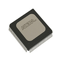
EPM9320RI208-20 Altera, EPM9320RI208-20 Datasheet - Page 19

EPM9320RI208-20
Manufacturer Part Number
EPM9320RI208-20
Description
Manufacturer
Altera
Datasheet
1.EPM9320RI208-20.pdf
(46 pages)
Specifications of EPM9320RI208-20
Family Name
MAX 9000
Memory Type
EEPROM
# Macrocells
320
Number Of Usable Gates
6000
Frequency (max)
100MHz
Propagation Delay Time
23ns
Number Of Logic Blocks/elements
20
# I/os (max)
132
Operating Supply Voltage (typ)
5V
In System Programmable
Yes
Operating Supply Voltage (min)
4.5V
Operating Supply Voltage (max)
5.5V
Operating Temp Range
-40C to 85C
Operating Temperature Classification
Industrial
Mounting
Surface Mount
Pin Count
208
Package Type
RQFP
Lead Free Status / Rohs Status
Not Compliant
Available stocks
Company
Part Number
Manufacturer
Quantity
Price
Part Number:
EPM9320RI208-20
Manufacturer:
ALTERA/阿尔特拉
Quantity:
20 000
Altera Corporation
In-System
Programma-
bility (ISP)
The VCCIO pins can be connected to either a 3.3-V or 5.0-V power supply,
depending on the output requirements. When the VCCIO pins are
connected to a 5.0-V power supply, the output levels are compatible with
5.0-V systems. When the VCCIO pins are connected to a 3.3-V power
supply, the output high is at 3.3 V and is therefore compatible with 3.3-V
or 5.0-V systems. Devices operating with V
incur a nominally greater timing delay of t
MAX 9000 devices can be programmed in-system through a 4-pin JTAG
interface. ISP offers quick and efficient iterations during design
development and debug cycles. The MAX 9000 architecture internally
generates the 12.0-V programming voltage required to program EEPROM
cells, eliminating the need for an external 12.0-V power supply to program
the devices on the board. During ISP, the I/O pins are tri-stated to
eliminate board conflicts.
ISP simplifies the manufacturing flow by allowing the devices to be
mounted on a printed circuit board with standard pick-and-place
equipment before they are programmed. MAX 9000 devices can be
programmed by downloading the information via in-circuit testers,
embedded processors, or the Altera BitBlaster, ByteBlaster, or
ByteBlasterMV download cable. (The ByteBlaster cable is obsolete and has
been replaced by the ByteBlasterMV cable, which can interface with 2.5-V,
3.3-V, and 5.0-V devices.) Programming the devices after they are placed
on the board eliminates lead damage on high pin-count packages (e.g.,
QFP packages) due to device handling. MAX 9000 devices can also be
reprogrammed in the field (i.e., product upgrades can be performed in the
field via software or modem).
In-system programming can be accomplished with either an adaptive or
constant algorithm. An adaptive algorithm reads information from the
unit and adapts subsequent programming steps to achieve the fastest
possible programming time for that unit. Because some in-circuit testers
platforms have difficulties supporting an adaptive algorithm, Altera
offers devices tested with a constant algorithm. Devices tested to the
constant algorithm have an “F” suffix in the ordering code.
MAX 9000 Programmable Logic Device Family Data Sheet
OD2
CCIO
instead of t
levels lower than 4.75 V
OD1
.
19


