HW1M-LF2020-20 IDEC, HW1M-LF2020-20 Datasheet
HW1M-LF2020-20


Related parts for HW1M-LF2020-20


HW1M-LF2020-20 Summary of contents
Page 1
HW Series Control Units ...
Page 2
HW Control Units (Selection Guide) Series Function Emergency Stop Switch (Unibody Type) Category ø40mm Mushroom ø40mm Mushroom Shape Type HW1E-BV4 Page 9 Function Emergency Stop Switch Pushlock Key Reset Category ø40mm Mushroom ø40mm Mushroom Shape Type HW1B-X4 Page 12 ...
Page 3
... Control Units (Selection Guide) Series ø40mm Mushroom HW3L-M3 HW1L-M4 HW3L-A3 HW1L- Pushbutton Selector Key HW1K HW1R 29 37 Emergency Stop Control Box w/Pushlock Turn Reset Switch HW1X-S HW1X- ø22 Illuminated Selector Switch (LED/Incandescent) HW1F 30 Mono-Lever Switch Standard Interlocking HW1M HW1M w/Pushlock Key Reset Switch HW1X- ...
Page 4
... For the control units listed below, the rated current (load switching current) is reduced to a half of the rated operational current of the con- tact block. The rated insulation voltage (600V) and the rated thermal current (10A) remain unchanged. • 3-position selector switches which contain following 3 in the Type No. and which have cam code Example: HW1S-3JT21N1 • All 4-position and 5-position selector switches • ...
Page 5
LED Illuminated Unit Specifications Color Code ➁ Unit A: amber G: green Pilot Light PW: pure white Illuminated Pushbutton R: red S: blue Illuminated Selector Switch W: white Y: yellow Incandescent Illuminated Unit Specifications Color Code ➁ Unit A: amber ...
Page 6
... IEC 60529 IP65 The minimum mounting centers are applicable to switches with one layer of contact blocks (two contact blocks). When two layers of contact blocks are mounted, determine the minimum mounting cen- ters in consideration of convenience for wiring. • Minimum Mounting Centers Unit ø ...
Page 7
... The Type No. development charts shown below can be used to specify control units other than those listed on the following pages. Gold-plated silver contacts are also available. Emergency Stop Switches For emergency stop purposes, these switches must contain at least one NC contact block. HW1B- -MAU ...
Page 8
... Transformer type contains an LED lamp (LSTD-6➁) or incandes- cent lamp (LS-6). Pushbutton Selectors HW1R-2 D 22N1 B -MAU Optional contact MAU: Gold-plated silver contact Button color code Contact code Circuit category Mono-Lever Switches HW1M - 1111 22N9 -MAU Optional contact MAU: Gold-plated silver contact Contact code Lever operation mode 8 ...
Page 9
... Emergency Stop Switches (Unibody Type) Specifications Contact Ratings Rated Insulation Voltage (Ui) Rated Thermal Current (Ith) Rated Operational Voltage (Ue) Resistive Load (AC-12) AC Rated 50/60 Hz Inductive Load (AC-15) Operational Resistive Load (DC-12) Current DC Inductive Load (DC-13) Note: The operational current represents the classification by making and breaking currents (IEC 60947-5-1). ...
Page 10
... Terminal Arrangement (Bottom View) • HW1E-BV4 Side .2 (NC) .3 (NO) .1 (NC) .4 (NO) (1NO-1NC) Package Quantity Used on HW1E emergency stop switches for preventing electrical shocks. 10 The HW-VL7 terminal cover is supplied with the HW1E. Type No. Lens Color HW1E-LV411Q0R Red only HW1E-LV402Q0R All dimensions in mm. ...
Page 11
... Yellow buttons cannot be used as emergency stop switches in compliance with EN standards. • When pressed, the button is held depressed. The button is released by turning clockwise. • Pushlock turn reset switches with one or three contact blocks contain a dummy block. • Safety lever lock HW9Z-LS is supplied with the switch. ...
Page 12
... When pressed, the button is held depressed. The button is released by turning the key clockwise. • Pushlock key reset switches with one or three contact blocks contain a dummy block. • Two identical keys and safety lever lock HW9Z-LS are supplied with the switch. ...
Page 13
... HW1B-Y2 29.4 The minimum mounting centers shown below are applicable to emergency stop switches with one layer of contact blocks (two contact blocks). When two layers of contact blocks are mounted, determine the minimum mounting centers in consider- ation of convenience for wiring. • Minimum Mounting Centers for Emergency Stop Switches ...
Page 14
... International industrial standards such as European Union Directive, IEC60204-1, and JIS B9960-1 require that emergency stop switches must be installed in the manner in which the operator can access and operate the switches easily, and prohibit the use of switch guards. The HW9Z-KG1 and HW9Z-KG2 switch guards are used for the emergency stop switches installed on semiconductor manufacturing equipment only ...
Page 15
Flush / Extended / Mushroom Types Operation Shape Type Flush HW1B-M1 HW1B-A1 Momentary Maintained Extended HW1B-M2 HW1B-A2 Momentary Maintained ø29mm Mushroom HW1B-M3 HW1B-A3 Momentary Maintained ø40mm Mushroom HW1B-M4 HW1B-A4 Momentary Maintained ø60mm Mushroom HW1B-M5 Momentary • Pushbuttons with one or ...
Page 16
HW Pushbuttons Series Square Flush / Square Extended Types Operation Shape Type Square Flush HW2B-M1 HW2B-A1 Momentary Maintained Square Extended HW2B-M2 HW2B-A2 Momentary Maintained • Pushbuttons with one or three contact blocks contain a dummy block. • Other contact ...
Page 17
Round Button with Square Bezel Type Operation Shape Type Round Flush with Square Bezel HW3B-M1 Momentary HW3B-A1 Maintained Round Extended with Square Bezel HW3B-M2 Momentary HW3B-A2 Maintained ø29mm Mushroom with Square Bezel HW3B-M3 Momentary HW3B-A3 Maintained • Pushbuttons with one ...
Page 18
HW Pilot Lights Series Round Flush / Dome / Square Flush Types Shape Lamp Round Flush Without Lamp Full Voltage HW1P-1 LED Incandescent (Photo: Full Voltage Type) Dome Without Lamp Full Voltage HW1P-2 LED (Photo: Full Voltage Type) Incandescent ...
Page 19
Round Flush Illuminated Pushbutton Shape Operation Type Round Flush HW1L-M1 HW1L-A1 Momentary Maintained • Color Code and Operating Voltage Code LED Illuminated Type Incandescent Illuminated Type ➁ Lens/LED Color Code Specify a lens/LED color code in Specify a lens color ...
Page 20
HW Illuminated Pushbuttons Series Round Extended Illuminated Pushbutton Shape Operation Type Round Extended HW1L-M2 HW1L-A2 Momentary Maintained • Color Code and Operating Voltage Code LED Illuminated Type Incandescent Illuminated Type ➁ Lens/LED Color Code Specify a lens/LED color code ...
Page 21
Round Extended with Full Shroud Illuminated Pushbutton Shape Operation Type Round Extended with Full Shroud HW1L-MF2 HW1L-AF2 Momentary Maintained • Color Code and Operating Voltage Code LED Illuminated Type Incandescent Illuminated Type ➁ Lens/LED Color Code Specify a lens/LED color ...
Page 22
HW Illuminated Pushbuttons Series Square Flush Illuminated Pushbutton Shape Operation Type Square Flush HW2L-M1 HW2L-A1 Momentary Maintained • Color Code and Operating Voltage Code LED Illuminated Type Incandescent Illuminated Type ➁ Lens/LED Color Code Specify a lens/LED color code ...
Page 23
Round Flush with Square Bezel Illuminated Pushbutton Shape Operation Type Round Flush with Square Bezel HW3L-M1 HW3L-A1 Momentary Maintained • Color Code and Operating Voltage Code LED Illuminated Type Incandescent Illuminated Type ➁ Lens/LED Color Code Specify a lens/LED color ...
Page 24
HW Illuminated Pushbuttons Series Mushroom (ø29mm) Illuminated Pushbutton Shape Operation Type ø29mm Mushroom HW1L-M3 HW1L-A3 Momentary Maintained • Color Code and Operating Voltage Code LED Illuminated Type Incandescent Illuminated Type ➁ Lens/LED Color Code Specify a lens/LED color code ...
Page 25
Mushroom (ø29mm) with Square Bezel Illuminated Pushbutton Shape Operation Type ø29mm Mushroom with Square Bezel HW3L-M3 HW3L-A3 Momentary Maintained • Color Code and Operating Voltage Code LED Illuminated Type Incandescent Illuminated Type ➁ Lens/LED Color Code Specify a lens/LED color ...
Page 26
HW Illuminated Pushbuttons Series Mushroom (ø40mm) Illuminated Pushbutton Shape Operation Type ø40mm Mushroom HW1L-M4 HW1L-A4 Momentary Maintained • Color Code and Operating Voltage Code LED Illuminated Type Incandescent Illuminated Type ➁ Lens/LED Color Code Specify a lens/LED color code ...
Page 27
Dimensions • Full Voltage Type Full Voltage Adapter M3.5 Terminal Screw Contact Block Locking Ring 49.4 (1 block) 1 contact block Full Voltage Adapter M3.5 Terminal Screw Contact Block Locking Ring 69.4 (2 blocks) 2 contact blocks Full Voltage Adapter ...
Page 28
... The rated insulation voltage and the rated thermal current remain unchanged. • Selector switches with one or three contact blocks contain a dummy block. Knob operator: White indicator on black body • Other contact arrangements are also available. See pages 33 through 36. ...
Page 29
... On the contact arrangement marked with ★ in the table above, the rated current (load switching current) is reduced to a half of the rated cur- rent of the contact block. The rated insulation voltage and the rated thermal current remain unchanged. • Key selector switches with one or three contact blocks contain a dummy block. • Cylinder cover: black, Cylinder: metal • ...
Page 30
... HW Illiminated Selector Switches Series Illuminated Selector Switches 90° 2-position / 60° 2-position Shape HW1F Contact Arrangement Chart Contact Operator Contact Block Position Code Mounting L R Type Position 1 NO Without Lamp LED (1NO-1NC) Incandescent 1 NO Without Lamp LED (2NO) Incandescent 1 NO Without Lamp ...
Page 31
... LED illuminated transformer types contain an LED lamp (LSTD-6➁, rated voltage 6V AC/DC). • Incandescent illuminated transformer types contain an incandescent lamp (LS-6, rated voltage 6V AC/DC). • Contact Block Mounting Position and Contact Arrangement Chart Full Voltage Adapter Full Voltage Type HW Illiminated Selector Switches Series Maintained Spring Return from Right Lamp HW1F-320Q0➁ ...
Page 32
... HW Selector Switches Series Dimensions: Selector Switches • Knob Operator 1 contact block • Key Operator Dimensions: Illuminated Selector Switches • Full Voltage Type • Transformer Type M.3.5 Terminal Screw Terminal Wiring • Arrows indicate access directions for wiring. 32 Panel Thickness 0 M3.5 Terminal ...
Page 33
HW Selector Switch Contact Arrangement Charts Series 90° 2-position (Maintained) / 60° 2-position (Spring Return) Operator Operator Availability Position L Contact Contact Block Code Mounting L C Type Position × × × × × × — Standard ...
Page 34
HW Selector Switch Contact Arrangement Charts Series 45° 3-position Operator Position Contact Contact Block Code Mounting Type Position (1NO-1NC 11N1 2 NO (1NO-1NC) 7S ★ ...
Page 35
HW Selector Switch Contact Arrangement Charts Series 45° 3-position Operator Position Contact Contact Block Code Mounting Type Position (4NO 40N1 ★ (4NO) ...
Page 36
HW Selector Switch Contact Arrangement Charts Series 45° 4-position Operator Position Contact Contact Block Code Mounting Type Position ★ (1NO-2NC) 4 Dummy 1 NC 04N3 ★ ...
Page 37
Pushbutton Selectors Circuit Contact Shape Category Code HW1R 11 (1NO-1NC) 20 (2NO (2NO-2NC) 20 (2NO) D 22N1 (2NO-2NC) 22N1 ★ E (2NO-2NC) 22N1 ★ F (2NO-2NC) 22N2 ★ N (2NO-2NC) 22N1 ★ T (2NO-2NC) • On the contact ...
Page 38
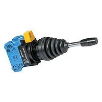
... Lever Operation Mode HW1M: Standard Order of Entry → → HW1M-L: Interlocking Up Right Down 1: Maintained 2: Spring returned 0: Blocked • The lever operator of the interlocking type HW1M-L is locked only in the center position. Dimensions M3.5 Terminal Screw 38 Positions 2-position 4-position 2-position 4-position • 2-position (Up/Down) Contact ...
Page 39
HW Series Accessories Nameplates • HWAM, HWAQ, HWAS, and HWAV Description Legend Plastic (black) Order marking plate HWAM separately. 1.5 mm thick Order marking plate Plastic (black) HWAQ separately. 1.5 mm thick Plastic (black) HWAS Blank 1.5 mm thick Blank ...
Page 40
... HW9Z-K11 HW9Z-K11 1 Dimensions (mm) the HW switch onto a panel. 110 cent lamps. 59 former, and also to install/remove the pilot light and illuminated pushbutton lens. 130 Generally used when using no nameplates on selector switches and pushbutton selectors. 1.5 TOP holes. ø29 ø25 holes. ø25.8 0 Gasket Locking Ring ...
Page 41
... Not suitable for outdoor use or where the units are subject to oil splash OC- OC-32 ) • Used to protect pushbuttons, illuminated pushbut- tons, selector switches, and key selector switches Panel Thickness 82.5 0.8 to 3.2 24 29.5 Waterproof Rubber Key Hole ø8 Gasket 0 ...
Page 42
HW Accessories and Replacement Parts Series Maintenance Parts Shape Button Round flush with round or square bezel Round extended with round or square bezel Square flush Square extended ø29mm mushroom ø40mm mushroom Lens (for pilot lights Round flush and ...
Page 43
HW Series Maintenance Parts LED Lamps (LSTD Type) Current Draw Operating Voltage AC 6V AC/DC ± ( (G, PW, S) 12V AC/DC ±10 24V AC/DC ±10 Incandescent Lamps (LS ...
Page 44
... Notes for Illuminated Pushbuttons The full shroud cannot be removed from the extended full shroud type. Safety Lever Lock IDEC strongly recommends using the safety lever lock (HW9Z-LS, yellow) to prevent heavy vibration or mainte- nance personnel from unlocking contacts series can be mounted vertically with a minimum spacing (70 mm for mono-lever switches) but spacing should be determined to ensure easy operation ...
Page 45
Instructions Replacement of Lens and Marking Plate • Removing 1. Remove the lens unit (color lens, marking plate, and lens holder) by inserting a screwdriver into the recess of the lens thorough the bezel. [Removing the Lens Unit] 2. Remove ...
Page 46
HW Instructions Series Instructions Replacement of Lamps Lamps can be replaced by using the lamp holder tool (OR- 55) from the front of the panel removing the contact block from the operator unit. • Removing the Lamps ...
Page 47
Instructions Tightening Torque for Terminal Screws Tighten the M3.5 terminal screws to a torque of 1.0 to 1.3 N·m . Installation of LED Illuminated Units 1. When using full voltage type LED illuminated units, pro- vide protection against electrical noise, ...
Page 48
HW Control Boxes Series Control Boxes Control Box (Gray Cover) Shape With Pushbutton HW1X-BM Shape No. of Positions Contact Code With Selector Switch HW1X-S 90° 2-position Maintained 45° 3-position Maintained Emergency Stop Control Box (Yellow Cover) Shape With Pushlock ...
Page 49
... Mechanical Life Selector switches: (minimum operations) Pushlock turn reset switches: Pushbuttons, momentary: Selector switches: Pushlock turn reset switches: 500,000 Electrical Life (Switching frequency) (minimum operations) ∗1 1,800 operations/h, duty ratio 40% ∗2 1,200 operations/h, duty ratio 40% ∗3 900 operations/h, duty ratio 40% Conduit Port ø ...
Page 50
HW Control Boxes Series Mounting Hole Layout 58 2-ø4.6 Applicable Terminal ø3.6 min. Tightening torque: 1.0 to 1.3 N·m A maximum of two pieces can be connected to one terminal. 4 max. 5.5 min. Nameplate Type No. Color: Black, ...
Page 51
... Specifications and other descriptions in this catalog are subject to change without notice. IDEC CORPORATION (USA) 1175 Elko Drive, Sunnyvale, CA 94089-2209, USA Tel: +1-408-747-0550, Toll Free: (800) 262-IDEC, Fax: +1-408-744-9055 E-mail: opencontact@idec.com, www.idec.com IDEC CANADA LIMITED Unit 22-151, Brunel Road Mississauga, Ontario, L4Z 1X3, Canada ...