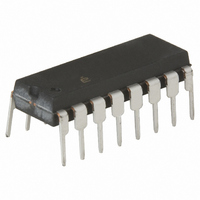
HI1-0539-5 Intersil, HI1-0539-5 Datasheet - Page 8

HI1-0539-5
Manufacturer Part Number
HI1-0539-5
Description
IC MULTIPLEXER 4X1 16CDIP
Manufacturer
Intersil
Datasheet
1.HI1-0539-5.pdf
(12 pages)
Specifications of HI1-0539-5
Function
Multiplexer
Circuit
1 x 4:1
On-state Resistance
850 Ohm
Voltage Supply Source
Dual Supply
Voltage - Supply, Single/dual (±)
±5 V ~ 18 V
Current - Supply
0.001mA
Operating Temperature
0°C ~ 75°C
Mounting Type
Through Hole
Package / Case
16-CDIP (0.300", 7.62mm)
Lead Free Status / RoHS Status
Contains lead / RoHS non-compliant
Available stocks
Company
Part Number
Manufacturer
Quantity
Price
Test Circuits and Waveforms
Application Information
General
The Hl-539 accepts inputs in the range -15V to +15V, with
performance guaranteed over the ±10V range. At these
higher levels of analog input voltage it is comparable to the
HI-509, and is plug-in compatible with that device (as well as
the Hl-509A). However, as mentioned earlier, the Hl-539 was
designed to introduce minimum error when switching low level
inputs.
Special care is required in working with these low level
signals. The main concern with signals below 100mV is that
noise, offset voltage, and other aberrations can represent a
large percentage error. A shielded differential signal path is
essential to maintain a noise level below 50µV
Low Level Signal Transmission
The transmission cable carrying the transducer signal is critical
in a low level system. It should be as short as practical and
rigidly supported. Signal conductors should be tightly twisted for
minimum enclosed area to guard against pickup of
electromagnetic interference, and the twisted pair should be
shielded against capacitively coupled (electrostatic)
interference. A braided wire shield may be satisfactory, but a
lapped foil shield is better since it allows only
leakage capacitance to ground per foot. A key requirement for
the transmission cable is that it presents a balanced line to
sources of noise interference. This means an equal series
impedance in each conductor plus an equally distributed
impedance from each conductor to ground. The result should
be signals equal in magnitude but opposite in phase at any
transverse plane. Noise will be coupled in phase to both
conductors, and may be rejected as common-mode voltage by
a differential amplifier connected to the multiplexer output.
FIGURE 7A. SINGLE-ENDED CROSSTALK TEST CIRCUIT
1kHz,
15V
P-P
350Ω
†
AD606 or BB3630, for Example
HI-539
8
INSTRUMENTATION
Unless Otherwise Specified T
AMPLIFIER
+
1
G = 1000
-
/
10
RMS
as much
.
†
FIGURE 7. CROSSTALK
HI-539
A
= 25
Coaxial cable is not suitable for low level signals because the
two conductors (center and shield) are unbalanced. Also,
ground loops are produced if the shield is grounded at both
ends by standard BNC connectors. If coax must be used, carry
the signal on the center conductors of two equal-length cables
whose shields are terminated only at the transducer end. As a
general rule, terminate (ground) the shield at one end only,
preferably at the end with greatest noise interference. This is
usually the transducer end for both high and low level signals.
Watch Small ∆V Errors
Printed circuit traces and short lengths of wire can add
substantial error to a signal even after it has traveled
hundreds of feet and arrived on a circuit board. Here, the
small voltage drops due to current flow through connections
of a few milliohms must be considered, especially to meet an
accuracy requirement of 12 bits or more.
Table 1 is a useful collection of data for calculating the effect
of these short connections. (Proximity to a ground plane will
lower the values of inductance.)
As an example, suppose the Hl-539 is feeding a 12-bit
converter system with an allowable error of ±
(±1.22mV). lf the interface logic draws 100mA from the 5V
supply, this current will produce 1.28mV across 6 inches of
#24 wire; more than the error budget. Obviously, this digital
current must not be routed through any portion of the analog
ground return network.
o
FIGURE 7B. DIFFERENTIAL CROSSTALK TEST CIRCUIT
C, V+ = +15V, V- = -15V, V
1kHz,
15V
P-P
350Ω
350Ω
†
AD606 or BB3630, for example
HI-539
AH
= 4V and V
INSTRUMENTATION
AL
= 0.8V (Continued)
AMPLIFIER
+
G = 1000
-
1
/
2
LSB
†


