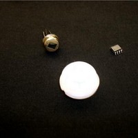
ZMOT0BSB1A0AG Zilog, ZMOT0BSB1A0AG Datasheet - Page 25

ZMOT0BSB1A0AG
Manufacturer Part Number
ZMOT0BSB1A0AG
Description
Processors - Application Specialized ZMB Nic RE200B-P Pyr Nic. NCL-9(26) Lens
Manufacturer
Zilog
Datasheet
1.ZMOT0BSB0A0AG.pdf
(65 pages)
Specifications of ZMOT0BSB1A0AG
Operating Supply Voltage
2.7 V to 3.6 V
Maximum Operating Temperature
+ 105 C
Mounting Style
SMD/SMT
Package / Case
SOIC-8
Core
Z8FS040
Number Of Timers
2
Processor Series
ZMOTION
Program Memory Size
4 KB
Program Memory Type
Flash
Lead Free Status / Rohs Status
Details
Available stocks
Company
Part Number
Manufacturer
Quantity
Price
Company:
Part Number:
ZMOT0BSB1A0AG
Manufacturer:
Zilog
Quantity:
3
Hardware Connection Requirements
PS028511-0112
This section describes the required external hardware connection for the ZMOTION MCU
Series.
Pins are automatically configured to their required function when the PIR engine is initial-
ized via the EPIR_INIT macro.
See
showing the required connections.
The device can be operated in SINGLE PYRO Mode to support one pyroelectric sensor, or
DUAL PYRO Mode to support two pyroelectric sensors. Both of these modes can be
operated in NORMAL or LOW SCAN RATE modes.
Depending on the application, there can be up to 3 connection requirements supporting
these modes:
Pyroelectric Sensor (PIR Sensor).
to the ANA2 input of the ADC. The ADC is configured for differential, buffered mode by
Zilog’s PIR technology. The sensor signal should be connected directly to the ADC input
with no additional signal conditioning circuitry unless specified by the pyroelectric sensor
manufacturer.
ADC V
connected to the “+” differential input of the ADC (ANA2), and the V
nected to the “–” differential input (ANA3). The 8 pin device has an internal connection
from V
tion is required. The 20 and 28 pin devices require an external connection from the V
out signal to the ADC– (ANA3) input.
Pyroelectric Passive Infrared Sensor #2.
in differential, buffered mode (the same as SINGLE PYRO Mode). The signal from the
second PIR sensor is connected to ANA3. The V
ANA3 (“–” ADC input). The fist PIR sensor is connected to the “+” ADC input (ANA2)
as it is in SINGLE PYRO Mode. The V
the external pin is unused in DUAL PYRO Mode.
Appendix A. Application Schematics
REF
REF
.
to ANA3 to support this configuration therefore no external hardware connec-
The on-chip V
REF
is configured for 1 V nominal. The PIR Sensor signal is
The signal from the PIR sensor is connected directly
REF
ZMOTION™ Detection and Control Family
on page 43 for example schematic diagrams
In DUAL PYRO Mode, the ADC is still used
signal is still used internally for the ADC, but
REF
signal is no longer connected to
Hardware Connection Requirements
Product Specification
REF
signal is con-
REF
18


