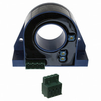
AC/DC Current Transducer DHR-C10
The transducer for the electronic measurement of DC & distorted AC
waveform currents, with galvanic isolation between the primary circuit
(power) and the secondary circuit (measurement). True RMS 0-10V
voltage output.
DC & AC Current
R
V
I
V
Î
X
e
V
TCV
TCV
t
BW
T
T
m
IPxx
Notes :
100518/19
Primary Nominal
C
P
r
A
S
C
SL
L
OE
L
I
PN
Electrical data
Performance data
General data
OE
OUT
(A.t.RMS)
1000
500
600
100
200
300
400
1)
2)
Load resistance
Supply voltage
Current consumption
Output voltage limitation (0 - 10 V)
Overload capability (Ampere Turns)
Accuracy @ I
Linearity error (1% of I
Electrical offset voltage, T
Temperature coefficient of V
Temperature coefficient of V
Response time to 90 % of I
Frequency bandwidth (± 1 dB)
Surrounding operating temperature
Surrounding storage temperature
Mass
Protection degree
The Max. Peak AC Current is the highest peak level of the primary
signal that is taken into account for accurate True RMS calculation. Yet
the device is designed for maximum continuous True RMS value equal to
I
According to the UL 508 Standard for Safety for Industrial Control
Equipment the primary current must not exceed 475 A.t.RMS through the
transducer hole.
PN
2)
2)
2)
, whereas the output is limited by the above specified output limitation.
Primary AC Current
Max. Peak Value
PN
, T
A
LEM reserves the right to carry out modifications on its transducers, in order to improve them, without prior notice.
600
600
1000
1000
1800
1800
1800
I
= 25°C (excluding offset)
P
(A)
PN
.. ± I
A
PN
= 25°C
OE
OUT
PN
step
1)
)
( 0..+60 °C)
(-40..+70 °C)
(% of reading)
Output voltage
V
(Analog)
OUT
0-10
0-10
0-10
0-10
0-10
0-10
0-10
(VDC)
≥ 10
+ 20 .. 50
30
< 14
30000
< ± 1
< ± 1.0
< ± 1.0
± 2.0
± 4.0
± 0.1
< 150
DC 20..6000
- 40 .. + 70
- 40 .. + 85
260
IP20
DHR 1000 C10
DHR 100 C10
DHR 200 C10
DHR 300 C10
DHR 400 C10
DHR 500 C10
DHR 600 C10
Type
% of I
% of I
% of I
mV/K
mV/K
V DC
%/K
mA
ms
kW
A.t
Hz
°C
°C
PN
PN
PN
V
g
I
Features
●
●
●
●
●
Advantages
●
●
●
Applications
●
●
●
Application domain
●
PN
VFD and SCR waveforms current
measurement
True RMS output
Panel mounting
Eliminates insertion loss
Isolated plastic case recognized
according to UL94-V0
Large aperture for cable up to
Ø32mm
High isolation between primary
and secondary circuits
Easy installation
VFD Controlled Loads
VFD output indicates how the
motor and attached load are
operating.
SCR Controlled Loads
Acurate measurement of phase
angle fired or burst fired (time
proportioned) SCRs. Current
measurement gives faster
response than temperature
measurement.
Switching Power Supplies and
Electronic Ballasts
True RMS sensing is the most
accurate way to measure power
supply or ballast input power.
Energy and Automation
= 100 .. 1000 A
www.lem.com
Page 1/4


