CKSR 6-NP LEM USA Inc, CKSR 6-NP Datasheet - Page 8
CKSR 6-NP
Manufacturer Part Number
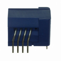
CKSR 6-NP
Description
SENSOR CURRENT 6A 5V MOD
Manufacturer
LEM USA Inc
Series
CKSRr
Datasheet
1.CKSR_25-NP.pdf
(24 pages)
Specifications of CKSR 6-NP
Current - Sensing
6A
Accuracy
±0.8%
Sensitivity
104.2mV/A
Current - Supply
-
Sensor Type
Flux Gate
Voltage - Supply
4.75 V ~ 5.25 V
Output
0 ~ 5 VDC
Frequency
300kHz
Response Time
300ns
Polarization
Bidirectional
Operating Temperature
-40°C ~ 105°C
Package / Case
Module
Lead Free Status / Rohs Status
Lead free / RoHS Compliant
Other names
398-1095-5


Electrical data
CAS / CASR / CKSR current transducers series have been
designed to work with a single
nominal current measurements from
This is a common power supply used in the power electronics
word to make working the various µprocessors, or DSPs or
ADCs (Analog Digital Converters) ect.
The models provide an analogue voltage output referenced
around a reference voltage.
By default, this reference voltage is the internal reference
voltage used inside the transducer: 2.5 V + a certain tolerance
(please see adequate data sheet according to the model).
Then, at the output, these 2.5 V provided at no primary
current can be considered as a virtual “0” V.
The gain is defined in order to get
model used (CAS or CASR or CKSR, 6 or 15 or 25 or 50 A
models).
The output voltage range is limited to between 0.375 V for the
negative current range and 4.625 V for the positive current
range centred around 2.5 V when external reference voltage
is not used.
The positive and negative voltage variation spans are each
of 2.125 V and fluctuate around the internal voltage reference
fixed at 2.5 V.
To define the measuring range, just divide the possible max
voltage variation span (positive or negative) by the gain
defined by the concerned model.
In general,
more than 3 times the nominal
For the 50 A models (CAS 50-NP, CASR 50-NP and CKSR
50-NP), the current measuring range is limited to +/- 150 A
(nevertheless 3 times the nominal current) (due to some
current limitations inside the transducer) meaning only
1.875 V as positive and negative variation spans, resulting
in a minimum output voltage of 0.625 V for –150 A and in a
maximum output voltage of 4.375 V for +150 A.
However, for these 50 A models, the limits for output voltage
rails remain +0.375 V and +4.625 V.
With the CASR and CKSR models, the internal voltage
reference is provided on a separate secondary additional pin
called V
This pin is a direct access to the voltage reference used
inside set around 2.5 V.
The Ref pin has two basic functional modes:
The first mode is called
primary current of 0 A, the output voltage is equal to the
8
REF
what is not the case with the CAS models.
the measuring range provided for each model is
“Ref out
current.
+ 5 V power supply
0.625 V at I
mode”. In this mode, for a
6 to 50 A
PN
RMS
whatever the
.
to cover
RMS
voltage at the Ref pin + an offset depending to the model
used (between the voltage output and the Ref pin).
The voltage provided at the Ref pin (Typically 2.5 V) stays
stable although the primary current changes.
The second mode is called
can apply an external voltage to the Ref pin to overdrive the
internal voltage reference. The minimum external voltage is
0 V and maximum 4 V. However, this mode defines different
measuring ranges according to the level of the external
voltage reference used (0 to 4 V) and according to the model
used (6, 15, 25 or 50 A model).
For more information on these 2 modes, please refer to the
chapter “Application advice”.
With zero primary current, the
With more than zero primary current, the transducer
consumes 20 mA max + (the primary current divided by the
number of turns used by the transducer: I
Accuracy
Using a Closed Loop Fluxgate technology allows reaching
accuracy that was impossible with traditional Closed Loop
Hall effect based technology (even with a dedicated ASIC).
Some applications required higher accuracy especially for
lower offset and gain drifts in temperature ranges.
CAS / CASR / CKSR models achieve an
of I
accuracy at
CAS: 2.5 to 3 % of I
CASR: 1.2 to 1.8 % of I
CKSR: 1.2 to 1.8 % of I
As you can see, the accuracy of the CAS is less good as the
CASR and CKSR models.
This is explained as follows: The CAS models do not provide
the internal voltage reference outside and then the voltage
output integrating the voltage reference inaccuracy.
What is not the case with the CASR and CKSR models
providing their internal voltage reference outside or being
able to feed their internal voltage reference with an external
voltage reference. When using both these last models (CASR
and CKSR), the output (V
to the voltage available on the voltage reference pin (which
one is used as reference for the whole electronic of the
application).
The voltage reference value available on this pin being well
known and under control (used and usually controlled by
the microcontroller or DSP), the microcontroller can easily
remove the initial offset at +25°C at no primary current.
PN
at +25°C
+85°C:
regardless of the model and the following
OUT
PN
“Ref in
) is usually measured referenced
PN
PN
consumption
mode”. In this mode, you
P
accuracy of 0.8 %
/ Ns).
is max 20 mA.
Related parts for CKSR 6-NP
Image
Part Number
Description
Manufacturer
Datasheet
Request
R

Part Number:
Description:
SENSOR CURRENT 25A 5V MOD
Manufacturer:
LEM USA Inc
Datasheet:

Part Number:
Description:
SENSOR CURRENT 15A 5V MOD
Manufacturer:
LEM USA Inc
Datasheet:

Part Number:
Description:
SENSOR CURRENT 50A 5V MOD
Manufacturer:
LEM USA Inc
Datasheet:

Part Number:
Description:
SENSOR CURRENT 200A TH
Manufacturer:
LEM USA Inc
Datasheet:


Part Number:
Description:
FHS 40 PCB KIT 30/78A
Manufacturer:
LEM USA Inc
Datasheet:

Part Number:
Description:
FHS 40 PCB KIT 16/30A
Manufacturer:
LEM USA Inc
Datasheet:

Part Number:
Description:
FHS 40 PCB KIT 16/55A
Manufacturer:
LEM USA Inc
Datasheet:

Part Number:
Description:
FHS 40 PCB W/JUMPER KIT 10/10A
Manufacturer:
LEM USA Inc
Datasheet:

Part Number:
Description:
FHS 40 PCB KIT 5/16A
Manufacturer:
LEM USA Inc
Datasheet:

Part Number:
Description:
FHS 40 PCB KIT 5/11A
Manufacturer:
LEM USA Inc
Datasheet:

Part Number:
Description:
TRANSFORM CURR 100A SPLIT CORE
Manufacturer:
LEM USA Inc
Datasheet:

Part Number:
Description:
TRANSFORM CURRENT 50A SPLIT CORE
Manufacturer:
LEM USA Inc
Datasheet:

Part Number:
Description:
SENSOR CURRENT 20A 5V UNI SMD
Manufacturer:
LEM USA Inc
Datasheet:

Part Number:
Description:
SENSOR CURRENT 15A 5V UNI SMD
Manufacturer:
LEM USA Inc
Datasheet: