XCARD XC-1 XMOS, XCARD XC-1 Datasheet - Page 7
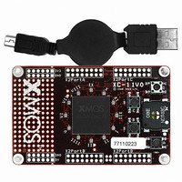
XCARD XC-1
Manufacturer Part Number
XCARD XC-1
Description
BOARD DEV KIT XS1-G4
Manufacturer
XMOS
Series
XCore™r
Type
MCUr
Datasheets
1.XS1-G04B-FB144-C4.pdf
(22 pages)
2.XCARD_XC-1.pdf
(2 pages)
3.XCARD_XC-1.pdf
(21 pages)
4.XCARD_XC-1.pdf
(17 pages)
Specifications of XCARD XC-1
Contents
Board, Cable
Lead Free Status / Rohs Status
Lead free / RoHS Compliant
For Use With/related Products
XS1-G4
Other names
880-1013


XC-1 Hardware Manual (1.3.2)
The I/O pins of processor 2 are brought out to expansion areas on both sides of the
Three of the expansion headers provide a bank of 12 I/O pins, while the fourth
5 I/O Expansion Areas [E]
card. These areas have 0.1” pitch plated through holes and are suitable for use with
IDC headers. To provide maximum flexibility, no headers are fitted, allowing the
most suitable type to be selected depending on the design. The routing of the I/O
and power pins in the expansion headers is shown below.
provides a bank of eight I/O pins. The pins are mapped to the ports as described in
the table on the next page.
X2D19
X2D17
X2D15
X2D13
X2D43
X2D41
X2D39
X2D37
X D23
X D21
2
2
GND
GND
GND
GND
NC
NC
16
16
2
2
15
15
1
1
5V
X2D22
X2D20
X2D18
3V3
X2D16
X2D14
X2D12
5V
NC
NC
X2D42
3V3
X2D40
X2D38
X2D36
www.xmos.com
X2D24
X2
X2
X2D30
X2
X2
X2
X2D0
X2
X2
X2D6
X2
D34
D26
D28
D32
D10
3V3
3V3
D2
D4
D8
5V
5V
1
15
1
15
16
16
2
2
X D1
X D3
X D5
X2D7
X D9
X D11
GND
X D25
X D27
X D29
GND
X 2D31
X D33
X D35
GND
GND
2
2
2
2
2
2
2
2
2
2
7/17
Related parts for XCARD XC-1
Image
Part Number
Description
Manufacturer
Datasheet
Request
R

Part Number:
Description:
BOARD DEV KIT XS1-G4 ETHERNET
Manufacturer:
XMOS
Datasheet:

Part Number:
Description:
BOARD DEV KIT XS1-G4
Manufacturer:
XMOS
Datasheet:

Part Number:
Description:
DEV KIT EVENT-DRIVEN PROC XS1-L1
Manufacturer:
XMOS
Datasheet:

Part Number:
Description:
BOARD KIT XS1-G4 LED CTRL TILE
Manufacturer:
XMOS
Datasheet:

Part Number:
Description:
ADAPTER USB DEBUGGER JTAG XSYS2
Manufacturer:
XMOS
Datasheet:

Part Number:
Description:
IC MPU 32BIT SINGLE CORE 64LQFP
Manufacturer:
XMOS
Datasheet:

Part Number:
Description:
IC MPU 32BIT SINGLE CORE 64LQFP
Manufacturer:
XMOS
Datasheet:
Part Number:
Description:
IC MPU 32BIT SINGLE CORE 64LQFP
Manufacturer:
XMOS
Datasheet:

Part Number:
Description:
IC MPU 32BIT SINGLE CORE 64LQFP
Manufacturer:
XMOS
Datasheet:
Part Number:
Description:
IC MPU 32BIT SINGLE CORE 64LQFP
Manufacturer:
XMOS
Datasheet:

Part Number:
Description:
IC MPU 32BIT SINGLE CORE 128TQFP
Manufacturer:
XMOS
Datasheet:
Part Number:
Description:
IC MPU 32BIT SINGLE CORE 64LQFP
Manufacturer:
XMOS
Datasheet:
Part Number:
Description:
IC MPU 32BIT SINGLE CORE 128TQFP
Manufacturer:
XMOS
Datasheet:
Part Number:
Description:
IC MPU 32BIT SINGLE CORE 128TQFP
Manufacturer:
XMOS
Datasheet:

Part Number:
Description:
IC MPU 32BIT DUAL CORE 124QFN
Manufacturer:
XMOS
Datasheet: