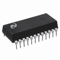
DP83910AN National Semiconductor, DP83910AN Datasheet - Page 2

DP83910AN
Manufacturer Part Number
DP83910AN
Description
IC SERIAL NETWRK INT CMOS 24-DIP
Manufacturer
National Semiconductor
Datasheet
1.DP83910AVNOPB.pdf
(12 pages)
Specifications of DP83910AN
Applications
Ethernet Network
Interface
Serial
Voltage - Supply
4.75 V ~ 5.25 V
Package / Case
24-DIP (0.300", 7.62mm)
Mounting Type
Through Hole
Lead Free Status / RoHS Status
Contains lead / RoHS non-compliant
Other names
*DP83910AN
Available stocks
Company
Part Number
Manufacturer
Quantity
Price
Part Number:
DP83910AN
Manufacturer:
NS/国半
Quantity:
20 000
2 0 Block Diagram
3 0 Functional Description
The DP83910A consists of five main logical blocks
a) The oscillator generates the 10 MHz transmit clock signal
b) The Manchester encoder accepts NRZ data from the
c) The Manchester decoder receives Manchester data from
d) The collision translator indicates to the controller the
e) The loopback circuitry when asserted routes the data
3 1 OSCILLATOR
The oscillator is controlled by a 20 MHz parallel resonant
crystal connected between X1 and X2 or by an external
clock on X1 The 20 MHz output of the oscillator is divided
by 2 to generate the 10 MHz transmit clock for the control-
ler The oscillator also provides internal clock signals to the
encoding and decoding circuits
If a crystal is connected to the DP83910A it is recommend-
ed that the circuit shown in Figure 1 be used and that the
components used meet the following
Crystal XT1 AT cut parallel resonant crystal
C1 C2 Load Capacitor 27 pF
The resistor R1 in Figure 1 may be required in order to
minimize frequency drift due to changes in the V
voltage If R1 is required it’s value must be carefully select-
ed R1 decreases the loop gain Thus if R1 is made too
large the loop gain will be greatly reduced and the crystal
will not oscillate If R1 is made too small normal variations
in the V
specification As the first rule of thumb the value of R1
Series Resistance
Specified Load Capacitance 13 5 pF
Accuracy 0 005% (50 ppm)
for system timing
controller encodes the data to Manchester and trans-
mits it differentially to the transceiver through the differ-
ential transmit driver
the transceiver converts it to NRZ data and clock pulses
and sends it to the controller
presence of a valid 10 MHz collision signal to the PLL
from the Manchester encoder back to the PLL decoder
CC
may cause the oscillation frequency to drift out of
s
10
CC
supply
2
Note 1 The resistor R1 may be required in order to minimize frequency drift
due to changes in the V
should be made equal to five times the motional resistance
of the crystal
The motional resistance of 20 MHz crystals is usually in the
range of 10
for R1 should be in the range of 50 – 150
The decision of whether or not to include R1 should be
based upon measured variations of crystal frequency as
each of the circuit parameters is varied
According to the IEEE 802 3 standard the entire oscillator
circuit (crytsal and amplifier) must be accurate to 0 01%
When using a crystal the X1 pin is not guaranteed to pro-
vide a TTL compatible logic output and should not be used
to drive external standard logic If additional logic needs to
be driven then an external oscillator should be used as
described in the following
3 2 OSCILLATOR MODULE OPERATION
If the designer wishes to use a crystal clock oscillator one
that provides the following should be employed
1) TTL or CMOS output with a 0 01% frequency tolerance
2) 40%– 60% duty cycle
3)
t
2 TTL load output drive (I
FIGURE 1 Crystal Connection to DP83910A
(see text for component values)
to 30
CC
See text description
This implies that a reasonable value
OL
e
3 2 mA)
TL F 9365 – 2
TL F 9365– 15


