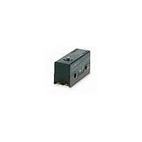
DZ-10GW22-1A Omron, DZ-10GW22-1A Datasheet - Page 5

DZ-10GW22-1A
Manufacturer Part Number
DZ-10GW22-1A
Description
Basic / Snap Action / Limit Switches BASIC SWITCH
Manufacturer
Omron
Series
DZr
Datasheet
1.DZ-10GW22-1A.pdf
(8 pages)
Specifications of DZ-10GW22-1A
Actuator
Roller Lever
Operating Force
400 g
Contact Form
DPDT
Contact Rating
10 Amps at 250 Volts
Termination Style
Solder
Mounting
Panel
Lead Free Status / Rohs Status
Details
Hinge Roller Lever
Precautions
■ Cautions
Terminal Connection
When soldering lead wires to the Switch, make sure that the capacity
of the soldering iron is 60 W maximum. Do not take more than 5 s to
solder any part of the Switch. Improper soldering may cause abnor-
mal heat radiation from the Switch and the Switch may burn.
The characteristics of the Switch will deteriorate if a soldering iron
with a capacity of more than 60 W is applied to any part of the Switch
for 6 s or more.
Operation
Make sure that the switching frequency or speed is within the speci-
fied range.
1. If the switching speed is extremely slow, the contact may not be
2. If the switching speed is extremely fast, switching shock may
DZ-10GV22-1B
DZ-10GW2-1B
DZ-10GV2-1B
switched smoothly, which may result in a contact failure or contact
welding.
damage the Switch soon. If the switching frequency is too high,
the contact may not catch up with the speed.
t = 1 (stainless-steel lever)
PT
OP
PT
OP
19.7 17.7
4.36
14.5
14.5
4.2
4.36
+0.1
–0.05 dia.
4.2
4.36
4.2
+0.075
–0.025
+0.1
–0.05 dia.
+0.075
–0.025
+0.075
–0.025
+0.1
–0.05
dia.
48.4R
t = 1 (Stainless-steel lever)
25.4±0.1
25.4±0.1
t = 1 (stainless-steel lever)
30.2R
25.4±0.1
28.4
49.2
48.4R
49.2
49.2
1.1
1.1
11.9
11.9
11.9
4.2
14.5
4.2
17.7
8.2
17.7
4.2
+0.075
–0.025 dia. hole
+0.075
–0.025
+0.075
–0.025
OP
19.7
8.2
19.7
dia. hole
8.2
dia. hole
FP
The rated permissible switching speed and frequency indicate the
switching reliability of the Switch.
The life of a Switch is determined at the specified switching speed.
The life varies with the switching speed and frequency even when
they are within the permissible ranges. In order to determine the life
of a Switch model to be applied to a particular use, it is best to con-
duct an appropriate life expectancy test on some samples of the
model under actual conditions.
Make sure that the actuator travel does not exceed the permissible
OT position. The operating stroke must be set to 70% to 100% of the
rated OT.
■ Correct Use
Mounting
Use M4 mounting screws with plane washers or spring washers to
securely mount the Switch. Tighten the screws to a torque of 1.18 to
1.47 N • m {12 to 15 kgf • cm}.
9.5 dia. x 4 (plastic roller)
17.45±0.2
9.5 dia. × 4 (plastic roller)
9.5 dia. × 4 (plastic roller)
17.45±0.2
17.45±0.2
Special-purpose Basic Switch
OF max.
RF min.
PT max.
OT min.
MD max.
OP
OF max.
RF min.
OT min.
MD max.
FP max.
OP
OF max.
RF min.
PT max.
OT min.
MD max.
OP
4.22 N {430 gf}
0.41 N {42 gf}
3 mm
0.13 mm
0.6 mm
29.4±0.8 mm
2.09 N {213 gf}
0.41 N {42 gf}
1.2 mm
3.3 mm
47.6 mm
31.8±0.8 mm
2.65 N {270 gf}
0.33 N {34 gf}
4 mm
0.26 mm
1.1 mm
29.4±0.8 mm
DZ
5


