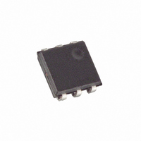
DS2406P+T&R Maxim Integrated Products, DS2406P+T&R Datasheet - Page 30

DS2406P+T&R
Manufacturer Part Number
DS2406P+T&R
Description
IC SW DL ADDRESS W/1K MEM 6-TSOC
Manufacturer
Maxim Integrated Products
Datasheet
1.DS2406.pdf
(32 pages)
Specifications of DS2406P+T&R
Applications
Remote Control, Remote Metering
Interface
1-Wire
Voltage - Supply
2.8 V ~ 6 V
Package / Case
6-TSOC
Mounting Type
Surface Mount
Lead Free Status / RoHS Status
Lead free / RoHS Compliant
PIO SINK CURRENT
NOTE: The sink current is production-tested at V
6V is guaranteed by design.
NOTES:
1. All voltages are referenced to ground.
2. V
3. V
4. Input load is to ground.
5. Leakage current is to ground.
6. Guaranteed by design, not production tested.
7. If the current at PIO-A reaches 200mA the gate voltage of the output transistor will be reduced to
8. PIO-A has a controlled turn-on output. The indicated currents are DC values. At V
9. V
10. Capacitance on the data pin could be 800pF when power is first applied. If a 5k Ω resistor is used to
11. The duration of the low pulse sent by the master should be a minimum of 2µs with a maximum value
12. The optimal sampling point for the master is as close as possible to the end time of the 15 μ s t
pull-up resistor and V
PIO pin should always be greater than or equal to V
limit the sink current to 200mA. The user-supplied circuitry should limit the current flow through the
PIO-transistor to no more than 100mA. Otherwise the DS2406 may be damaged.
higher the sink current typically reaches 80% of its DC value 1 µs after turning on the transistor.
pull up the data line to V
normal communications.
as short as possible to allow time for the pull-up resistor to recover the line to a high level before the
1-Wire device samples in the case of a Write 1 Low Time, or before the master samples in the case of
a Read Low Time.
period without exceeding t
time for the pull-up resistor to recover the line to a high level. For a Read-zero time slot it ensures
that a read will occur before the fastest 1-Wire devices(s) release the line (t
I SA , I SB
@ 0.4V
PUP
IH
CC
is a function of the chip-internal supply voltage. This voltage is determined by either the external
must be at least 4.0V if it is to be connected during a programming pulse.
, V
PUPA
100 mA
, V
90 mA
80 mA
70 mA
60 mA
50 mA
40 mA
30 mA
20 mA
10 mA
PUPB
= external pull-up voltage.
PUP
PUP
or the V
2.8V
RDV
, 5µs after power has been applied the parasite capacitance will not affect
. For the case of a Read-one time slot, this maximizes the amount of
CC
supply, whichever is higher. Without V
30 of 32
PUP
4V
= 2.8V; the specification for V
PUP
-0.3V.
5V
RELEASE
CC
6V
supply, V
PUP
max.
PIO-A
min.
max.
PIO-B
min.
= 0).
of 4V, 5V and
PUP
IH
V PUP
= 4.0V or
for either
RDV


