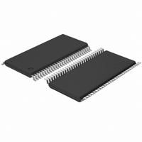
PCA9504ADGG,112 NXP Semiconductors, PCA9504ADGG,112 Datasheet - Page 21

PCA9504ADGG,112
Manufacturer Part Number
PCA9504ADGG,112
Description
IC GLUE CHIP 4 DUAL 56TSSOP
Manufacturer
NXP Semiconductors
Datasheet
1.PCA9504ADGG118.pdf
(29 pages)
Specifications of PCA9504ADGG,112
Applications
PC's, PDA's
Interface
I²C
Voltage - Supply
3 V ~ 5.25 V
Package / Case
56-TSSOP
Mounting Type
Surface Mount
Lead Free Status / RoHS Status
Lead free / RoHS Compliant
Other names
935267864112
PCA9504A
PCA9504A
PCA9504A
PCA9504A
1. Nominal timing values with tolerances are listed in the DC
Philips Semiconductors
NOTE:
2004 May 11
Timings should remain the same for both a 66 MHz or 33 MHz
CLK_IN input.
The boundary condition for INIT listed above, is a special case
where immediately following the FLUSH_OUT*, INIT_OUT* cycle,
the ICH2 asserts INIT* into the Glue Chip.
The boundary condition for GPO_FLUSH_CACHE* listed above,
is a special case where immediately following the first assertion of
GPO_FLUSH_CACHE*, the GPO is de-asserted, then re-asserted
again before the timings have had a chance to complete.
Glue chip 4
Characteristics table.
GPO_FLUSH_CACHE*
FLUSH_OUT_FWH*
FLUSH_OUT_CPU*
GPO_FLUSH_CACHE*
FLUSH_OUT_FWH*
FLUSH_OUT_CPU*
INIT_OUT*
INIT_OUT*
A20M*
INIT*
A20M*
Figure 13. Waveforms for boundary GPO_FLUSH_CACHE* Case
INIT*
Figure 12. Waveforms for Case 7
t1
t1
21
t1
t1
GPO_FLUSH_CACHE* – input to logic, GPO from the ICH2,
programmed active LOW.
INIT* – input to logic, INIT* signal from the ICH2.
A20M* – input to logic, A20M* signal from the ICH2.
FLUSH_OUT_CPU* – output of logic, route to CPU FLUSH* pin.
FLUSH_OUT_CPU* – output of logic, routed to FWH INIT* pin.
INIT_OUT* – output of logic, routed to CPU INIT* pin.
t1
t
t
t
t
t
SW00591
PCA9504A
SW00592
Product data


