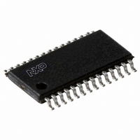
PCA9558PW,112 NXP Semiconductors, PCA9558PW,112 Datasheet - Page 13

PCA9558PW,112
Manufacturer Part Number
PCA9558PW,112
Description
IC I2C/SMBUS 8BIT 28-TSSOP
Manufacturer
NXP Semiconductors
Datasheet
1.PCA9558PW112.pdf
(27 pages)
Specifications of PCA9558PW,112
Applications
PC's, PDA's
Interface
I²C
Voltage - Supply
3 V ~ 3.6 V
Package / Case
28-TSSOP
Mounting Type
Surface Mount
Lead Free Status / RoHS Status
Lead free / RoHS Compliant
Other names
568-3399-5
935269433112
PCA9558PW
935269433112
PCA9558PW
NXP Semiconductors
PCA9558_4
Product data sheet
Fig 15. I
Fig 16. Read from 256-byte EEPROM and write to GPIO registers
M bytes where M
See
2
S
START condition
C-bus read operation from 256-byte EEPROM
(cont.)
1
Table 3
7.1.3.5 256-byte EEPROM write to GPIO
7.1.3.6 256-byte EEPROM write from GPIO
0
slave address
S
(re)START condition
S
START condition
0
for the needed command code.
1
1
1
A mode is available whereby a byte of data in the 256-byte EEPROM array can be written
to the GPIO (OP register). This is initiated by the I
indicating a read from the 256-byte EEPROM and write to the GPIO is sent, followed by
the word address of the data within the EEPROM array. Upon Acknowledge from the
slave, the data is sent to the GPIO. See
A mode is available whereby data in the GPIO (IP register) can be written to the 256-byte
EEPROM. This is initiated by the I
from the GPIO and write to the 256-byte EEPROM is sent, followed by the word address
for the data to be written. Once the slave has sent an Acknowledge, the master must send
a STOP condition. See
After the STOP condition, the E/W cycle starts, and the parts will not respond to any
request to access the EEPROM array until the cycle finishes, approximately 4 ms.
0
0
1
1.
slave address
slave address
0
0
1 A0 0
1
(cont.)
1
R/W
1
1
1 A0 1
acknowledge
A
S
1 A0 0
(re)START
condition
acknowledge
from slave
from slave
0
1
R/W
R/W
0
0
slave address
A
command byte
A
acknowledge
from slave
0
0
Rev. 04 — 14 April 2009
Figure
0
1
x
0
x
1
DATA N
command code
17.
0
x
1 A0 1
acknowledge
from slave
0
x
2
R/W
C-bus. In this mode, a control word indicating a read
Auto-Increment
word address
0
x
A
A
0
acknowledge
from slave
Figure
A
acknowledge
from master
a7
d7
1
data from 256-byte EEPROM
a6 a5 a4 a3 a2 a1 a0
d6 d5 d4 d3 d2 d1 d0
1
EEPROM address
16.
A
acknowledge
from slave
2
C-bus. In this mode, a control word
EEPROM address
DATA N + M
no acknowledge
Auto-Increment
acknowledge
no acknowledge
from master
word address
8-bit I
from slave
acknowledge
from master
from slave
NA
2
A
C-bus/SMBus I/O port
NA
(cont.)
A
P
STOP condition;
data latched into
GPIO register
PCA9558
002aad379
(cont.)
© NXP B.V. 2009. All rights reserved.
P
STOP
condition
002aad380
13 of 27


