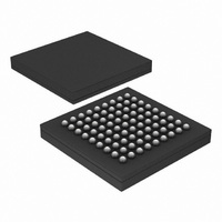
PX1011B-EL1/G,551 NXP Semiconductors, PX1011B-EL1/G,551 Datasheet - Page 12

PX1011B-EL1/G,551
Manufacturer Part Number
PX1011B-EL1/G,551
Description
IC PCI-EXPRESS X1 PHY 81-LFBGA
Manufacturer
NXP Semiconductors
Specifications of PX1011B-EL1/G,551
Package / Case
81-LFBGA
Applications
PCI Express MAX to PCI Express PHY
Interface
JTAG
Voltage - Supply
1.2 V
Mounting Type
Surface Mount
Input Voltage Range (max)
0.31 V
Maximum Operating Temperature
+ 70 C
Maximum Power Dissipation
300 mW
Minimum Operating Temperature
0 C
Mounting Style
SMD/SMT
Operating Supply Voltage
1.2 V
Supply Current (max)
28 mA
Lead Free Status / RoHS Status
Lead free / RoHS Compliant
Lead Free Status / RoHS Status
Lead free / RoHS Compliant, Lead free / RoHS Compliant
Other names
568-4715
935282113551
PX1011B-EL1/G-S
PX1011B-EL1/G-S
935282113551
PX1011B-EL1/G-S
PX1011B-EL1/G-S
Available stocks
Company
Part Number
Manufacturer
Quantity
Price
Company:
Part Number:
PX1011B-EL1/G,551
Manufacturer:
NXP Semiconductors
Quantity:
10 000
NXP Semiconductors
PX1011B
Product data sheet
The PHY begins to loopback data when the MAC asserts RXDET_LOOPB while doing
normal data transmission. The PHY stops transmitting data from the PXPIPE interface,
and begins to loopback received symbols. While doing loopback, the PHY continues to
present received data on the PXPIPE interface.
The PHY stops looping back received data when the MAC de-asserts RXDET_LOOPB.
Transmission of data on the parallel interface begins immediately.
The timing diagram of
example, the receiver is receiving a repeating stream of bytes, Rx-a through Rx-z.
Similarly, the MAC is causing the PHY to transmit a repeating stream of bytes Tx-a
through Tx-z. When the MAC asserts RXDET_LOOPB to the PHY, the PHY begins to
loopback the received data to the differential TX_P and TX_N lines.
The timing diagram of
normal mode. As soon as the MAC detects an electrical idle ordered-set, the MAC
de-asserts RXDET_LOOPB, asserts TXIDLE and changes the POWERDOWN signals to
state P1.
Fig 6.
•
•
The PHY continues to provide the received data on the PXPIPE interface, behaving
exactly like normal data reception.
The PHY transitions from normal transmission of data from the PXPIPE interface to
looping back the received data at a symbol boundary.
RXDET_LOOPB
RXDATA[7:0]
TXDATA[7:0]
TX_P, TX_N
Loopback start
RXCLK
TXCLK
All information provided in this document is subject to legal disclaimers.
Tx-m
Rx-c
Figure 6
Figure 7
Rev. 5 — 18 April 2011
shows example timing for beginning loopback. In this
shows an example of switching from loopback mode to
Tx-n
Rx-d
Tx-o
Rx-e
Tx-m
PCI Express stand-alone X1 PHY
Tx-p
Rx-f
Tx-n
PX1011B
Tx-q
Rx-g
© NXP B.V. 2011. All rights reserved.
Rx-e
002aac174
12 of 32


