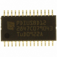
PDIUSBD12PWTM ST-Ericsson Inc, PDIUSBD12PWTM Datasheet - Page 14

PDIUSBD12PWTM
Manufacturer Part Number
PDIUSBD12PWTM
Description
IC USB INTRFC W/PARL BUS 28TSSOP
Manufacturer
ST-Ericsson Inc
Datasheet
1.PDIUSBD12PWTM.pdf
(40 pages)
Specifications of PDIUSBD12PWTM
Applications
USB Host/Peripheral Controller
Interface
Parallel
Voltage - Supply
3 V ~ 3.6 V, 4 V ~ 5.5 V
Package / Case
28-TSSOP
Mounting Type
Surface Mount
For Use With
D12 ISA PC EVAL KIT - EVAL KIT FOR PDIUSBD12 USB EPP
Lead Free Status / RoHS Status
Lead free / RoHS Compliant
Other names
568-1092-2
PDIUSBD12PW,118
PDIUSBD12PWDH-T
PDIUSBD12PW,118
PDIUSBD12PWDH-T
Available stocks
Company
Part Number
Manufacturer
Quantity
Price
Company:
Part Number:
PDIUSBD12PWTM
Manufacturer:
ST
Quantity:
4 500
Philips Semiconductors
PDIUSBD12_9
Product data sheet
11.2.2 Set Endpoint Enable
11.2.3 Set Mode
Code (Hex) — D8
Transaction — write 1 B
The generic or isochronous endpoints can only be enabled when the function is enabled
using the Set Address/Enable command.
Code (Hex) — F3
Transaction — write 2 B
The Set Mode command is followed by two data writes. The first byte contains
configuration bits. The second byte is the clock division factor byte.
Fig 5. Set Endpoint Enable command: bit allocation
Fig 6. Set Mode command, configuration byte: bit allocation
GENERIC OR ISOCHRONOUS ENDPOINTS: Logic 1 indicates that generic or isochronous
endpoints are enabled.
For bit allocation, see
X X
7 6 5 4 3 2
Rev. 09 — 11 May 2006
7 6 5 4 3 2
0
X X
0
Table
0 0
X X
5.
1
X
1
1
0
0
1
1
0
0
Power-on value
GENERIC/ISOCHRONOUS ENDPOINTS
reserved; write 0
USB peripheral controller with parallel bus
Power-on value
reserved
NO LAZYCLOCK
CLOCK RUNNING
INTERRUPT MODE
SoftConnect
reserved; write 0
ENDPOINT CONFIGURATION
© Koninklijke Philips Electronics N.V. 2006. All rights reserved.
004aaa799
004aaa798
PDIUSBD12
13 of 39


