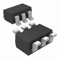
MAX9180EXT+T Maxim Integrated Products, MAX9180EXT+T Datasheet - Page 5

MAX9180EXT+T
Manufacturer Part Number
MAX9180EXT+T
Description
IC REPEATER LVDS SC70-6
Manufacturer
Maxim Integrated Products
Type
Repeaterr
Datasheet
1.MAX9180EXTT.pdf
(9 pages)
Specifications of MAX9180EXT+T
Tx/rx Type
LVDS
Delay Time
2.0ns
Voltage - Supply
3 V ~ 3.6 V
Current - Supply
10mA
Mounting Type
Surface Mount
Package / Case
SC-70-6, SC-88, SOT-363
Lead Free Status / RoHS Status
Lead free / RoHS Compliant
Capacitance - Input
-
(V
frequency = 200MHz, 50% duty cycle, R
Table 1. Function Table for LVDS Fail-Safe
Input (Figure 2)
Note:
Undriven open, short, or terminated
CC
PIN
1
2
3
4
5
6
= 3.3V, R
V
High = 450mV ≥ V
Low = -250mV ≥ V
ID
50mV
= (IN+ - IN-), V
INPUT, V
NAME
OUT+
OUT-
L
GND
< -50mV
V
> 50mV
IN+
IN-
= 100Ω ±1%, C
CC
V
ID
_______________________________________________________________________________________
800
750
700
650
600
550
500
450
400
ID
-50mV
OD
OD
OD
-40
400Mbps, Low-Jitter, Low-Noise LVDS
Inverting LVDS Output
Ground
Inverting LVDS Input
Noninverting LVDS Input
Power Supply. Bypass V
with a 0.01µF ceramic capacitor.
Noninverting LVDS Output
= (OUT+ - OUT-)
≥ 250mV
≥ -450mV
-15
L
= 10pF,
Pin Description
VS.
TRANSITION TIME
TEMPERATURE (°C)
t
TEMPERATURE
TLH
10
FUNCTION
O
, t
THL
= 50Ω, t
|
V
OUTPUT, V
Indeterminate
ID
35
|
Typical Operating Characteristics (continued)
= 0.2V, V
High
High
Low
Repeater in an SC70 Package
R
CC
60
= 1.5ns, and t
to GND
OD
CM
85
= 1.2V, T
F
= 1.5ns (0% to 100%), unless otherwise noted.)
600
500
400
300
200
100
The LVDS interface standard is a signaling method
intended for point-to-point communication over a con-
trolled-impedance medium, as defined by the ANSI/
TIA/EIA-644 and IEEE 1596.3 standards. The LVDS
standard uses a lower voltage swing than other com-
mon communication standards, achieving higher data
rates with reduced power consumption while reducing
EMI emissions and system susceptibility to noise.
The MAX9180 is a 400Mbps LVDS repeater intended
for high-speed, point-to-point, low-power applications.
The MAX9180 accepts an LVDS input and reproduces
an LVDS signal at the output. This device is capable of
detecting differential signals as low as 50mV and as
high as 1.2V within a 0 to 2.4V input voltage range. The
LVDS standard specifies an input voltage range of 0 to
2.4V referenced to ground.
Fail-safe is a feature that puts the output in a known
logic state (differential high) under certain fault condi-
tions. The MAX9180 outputs are differential high when
the inputs are undriven and open, terminated, or shorted
(Table 1).
0
A
25
= +25°C, unless otherwise noted. Signal generator output:
DIFFERENTIAL OUTPUT VOLTAGE
50
VS.
LOAD RESISTOR ( )
LOAD RESISTOR
75
100
Detailed Description
125
150
Fail-Safe
5


