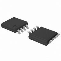
PCA9600DP,118 NXP Semiconductors, PCA9600DP,118 Datasheet - Page 8

PCA9600DP,118
Manufacturer Part Number
PCA9600DP,118
Description
IC BUS BUFFER DUAL BIDIR 8-TSSOP
Manufacturer
NXP Semiconductors
Type
Bufferr
Datasheet
1.PCA9600DP118.pdf
(30 pages)
Specifications of PCA9600DP,118
Package / Case
8-TSSOP
Tx/rx Type
I²C Logic
Delay Time
100ns
Capacitance - Input
10pF
Voltage - Supply
2.5 V ~ 15 V
Current - Supply
7.3mA
Mounting Type
Surface Mount
Logic Family
SDA, SCL
Supply Voltage (max)
15 V
Supply Voltage (min)
2 V
Maximum Operating Temperature
+ 85 C
Mounting Style
SMD/SMT
Interface
I2C Bus
Maximum Power Dissipation
300 mW
Minimum Operating Temperature
- 40 C
Output Current
2 mA
Output Voltage
15 V
Supply Current
5.5 mA
Logic Type
Bidirectional Bus Buffer
Lead Free Status / RoHS Status
Lead free / RoHS Compliant
For Use With
568-4704 - DAUGHTER CARD PCA9600 FOR OM6275
Lead Free Status / Rohs Status
Lead free / RoHS Compliant
Other names
568-4716-2
935285244118
PCA9600DP-T
PCA9600DP-T
935285244118
PCA9600DP-T
PCA9600DP-T
Available stocks
Company
Part Number
Manufacturer
Quantity
Price
Company:
Part Number:
PCA9600DP,118
Manufacturer:
Zilog
Quantity:
26
Part Number:
PCA9600DP,118
Manufacturer:
NXP/恩智浦
Quantity:
20 000
NXP Semiconductors
Table 6.
T
unless otherwise specified. Typical values are measured at V
PCA9600_4
Product data sheet
Symbol Parameter
Output logic LOW level
Pins SX and SY
V
Input logic switching threshold voltages
Pins SX and SY
V
V
Pins RX and RY
V
V
V
Logic level threshold difference
Thermal resistance
R
Bus release on V
V
amb
V/ T
V/ T
V
V/ T
OL
IL
th(IH)
IH
th(i)
IL
CC
th(j-pcb)
= 40 C to +85 C unless otherwise specified; voltages are specified with respect to GND with V
LOW-level output voltage
voltage variation with temperature
LOW-level input voltage
HIGH-level input threshold voltage
voltage variation with temperature
HIGH-level input voltage
input threshold voltage
LOW-level input voltage
voltage difference
thermal resistance from junction to
printed-circuit board
supply voltage
voltage variation with temperature
Characteristics
CC
failure
…continued
Rev. 04 — 11 November 2009
Conditions
on Standard-mode or
Fast-mode I
on 5 V Fm+ I
I
on normal I
on normal I
fraction of applied V
fraction of applied V
fraction of applied V
SX and SY; SX output LOW at
0.3 mA to SX input HIGH
maximum
SOT96-1 (SO8); average lead
temperature at board interface
SX, SY, TX and TY; voltage at
which all buses are to be
released at 25 C
Figure 9
SX
I
I
I
SX
SX
SX
= I
= I
= I
= I
SY
SY
SY
SY
= 0.3 mA to 3 mA
CC
= 3 mA;
= 0.3 mA;
= 7 mA
2
2
2
C-bus;
C-bus;
C-bus
2
C-bus
= 5 V and T
Figure 7
Figure 8
Figure 6
CC
CC
CC
Figure 5
amb
= 25 C.
[3]
[4]
Min
-
-
-
-
425
-
-
0.55V
-
-
50
-
-
-
Dual bidirectional bus buffer
CC
Typ
0.7
0.6
-
0
500
500
0
-
0.48V
-
-
127
-
4
CC
PCA9600
CC
© NXP B.V. 2009. All rights reserved.
= 2.5 V to 15 V
Max
0.74
0.65
1
-
-
580
-
-
-
0.4V
-
-
1
-
CC
8 of 30
Unit
V
mV
V
%/K
mV
mV
%/K
V
V
V
mV
K/W
V
%/K


