LM2502SM/NOPB National Semiconductor, LM2502SM/NOPB Datasheet - Page 20
LM2502SM/NOPB
Manufacturer Part Number
LM2502SM/NOPB
Description
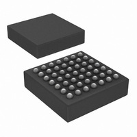
IC SER/DESER MPL DISPL 49-UFBGA
Manufacturer
National Semiconductor
Series
LMr
Datasheet
1.LM2502SMNOPB.pdf
(27 pages)
Specifications of LM2502SM/NOPB
Function
Serializer/Deserializer
Data Rate
307Mbps
Input Type
LVCMOS
Output Type
LVCMOS
Number Of Inputs
22
Number Of Outputs
3
Voltage - Supply
1.7 V ~ 3.3 V
Operating Temperature
-30°C ~ 85°C
Mounting Type
Surface Mount
Package / Case
49-UFBGA
Lead Free Status / RoHS Status
Lead free / RoHS Compliant
Other names
LM2502SMTR
Available stocks
Company
Part Number
Manufacturer
Quantity
Price
Company:

Part Number:
LM2502SM/NOPB
Manufacturer:
Texas Instruments
Quantity:
10 000


www.national.com
Functional Description
LM2502 Features and Operation
POWER SUPPLIES
The V
the same potential between 2.9V and 3.3V. V
the logic interface and may be powered between 1.7 and
3.3V to be compatible with a wide range of host and target
devices. V
V
up, all rails should power up at the same time, or V
V
POWER DOWN/OFF
The Master and the Slave provide a PD* pin to save power
when the link is not needed. A Low on this pin will power
down the entire device and turn off the line current to MD0,
MD1, and MC.
During power up, the PD* inputs should be held LOW and
released once power is stable and within specification. The
Slave PD* may be released first or at the same time as the
Master’s PD
releasing PD*. If the Powerdown state is not required, the
PD
power up smooth through the logic threshold region.
In Powerdown (PD
to:
Master:
INTR = L
Slave depends on mode configuration - see Table 9.
T10
T11
T12
T13
T14
T15
T16
DDA
DDA
No.
T1
T2
T3
T4
T5
T6
T7
T8
T9
*
pins maybe connected to V
DDcore
should lead.
applied as V
DDIO
MasterOUT
MasterOUT
MasterOUT
MasterOUT
MasterOUT
MasterIN
MasterIN
and V
*
Master
Master
Master
Slave
Slave
Slave
Slave
Slave
Slave
pin. CLK (Master) should be applied prior to
should not be powered up without V
DDA
*
DDcore
= GND) the following outputs are driven
(MPL and PLL) must be connected to
Set Up Time (A/D, RD
Hold Time (A/D, RD
Master Latency
Slave Latency
Read* Delay
Read Low Pulse Width
Data Set Up Time
Data Hold Time
Slave Read Latency
MST Read Latency and INTR Delay
Data Delay
Data Valid after Strobe
RD* active pulse width
INTR De-assert
Recovery Time
INTR Response, (Note 5)
biases the IO ring. During power
DDIO
, however V
TABLE 8. READ — Intel µP Interface Parameters
(Continued)
Parameter
*
) and Data Off Time
DDIO
*
DDIO
) and Data On Time
powers
DDcore
DDcore
should
/
/
20
BYPASS RECOMMENDATIONS
Bypass capacitors should be placed near the power supply
pins of the device. Use high frequency ceramic (surface
mount recommended) 0.1 µF capacitors. A 2.2 to 4.7 µF
Tantalum capacitor is recommended near the Master (SER)
V
wide traces and use dual or larger via to reduce resistance
and inductance of the feeds. Utilizing a thin spacing between
power and ground planes will provide good high frequency
bypass above the frequency range where most typical sur-
face mount capacitors are less effective. To gain the maxi-
mum benefit from this, low inductance feed points are impor-
tant. Also, adjacent signal layers can be filled to create
additional capacitance. Minimize loops in the ground returns
also for improved signal fidelity and lowest emissions.
UN-USED/OPEN PINS
Unused inputs must be tied to the proper input level — do not
float them. Unused outputs should be left open to minimize
power dissipation.
PHASE-LOCKED LOOP
When the LM2502 is configured as a Master, a PLL is
enabled to generate the serial link clock. The Phase-locked
loop system generates the serial data clock at several mul-
tiples of the input clock. The PLL operates with an input clock
DDA
Pin
AD
Data[n]
CLK
CS1
CS2
MF0
MF1
pin for PLL bypass. Connect bypass capacitors with
Min
20
15
20
TABLE 9. SLV Output in Powerdown
*
*
5
0
18.6
Typ
15
12
15
5
6
1
6
4
5
5
SLV
i80
H
H
H
H
L
L
L
Max
m68
SLV
H
H
H
H
H
L
L
MC Cycles
MC Cycles
MC Cycles
MC Cycles
MC Cycles
MC Cycles
MC Cycles
MC Cycles
Units
ns
ns
ns
ns
ns
ns
ns
ns
Related parts for LM2502SM/NOPB
Image
Part Number
Description
Manufacturer
Datasheet
Request
R

Part Number:
Description:
Mobile Pixel Link Mpl Display Interface Serializer And Deserializer
Manufacturer:
National Semiconductor Corporation
Datasheet:

Part Number:
Description:
National Semiconductor [8-Bit D/A Converter]
Manufacturer:
National Semiconductor
Datasheet:
Part Number:
Description:
National Semiconductor [Media Coprocessor]
Manufacturer:
National Semiconductor
Datasheet:
Part Number:
Description:
Digitally Controlled Tone and Volume Circuit with Stereo Audio Power Amplifier, Microphone Preamp Stage and National 3D Sound
Manufacturer:
National Semiconductor
Datasheet:
Part Number:
Description:
Digitally Controlled Tone and Volume Circuit with Stereo Audio Power Amplifier, Microphone Preamp Stage and National 3D Sound
Manufacturer:
National Semiconductor
Datasheet:
Part Number:
Description:
AC97 Rev 2 Codec with Sample Rate Conversion and National 3D Sound
Manufacturer:
National Semiconductor
Part Number:
Description:
Manufacturer:
National Semiconductor
Datasheet:
Part Number:
Description:
Manufacturer:
National Semiconductor
Datasheet:
Part Number:
Description:
General Purpose, Low Voltage, Low Power, Rail-to-Rail Output Operational Amplifiers
Manufacturer:
National Semiconductor
Datasheet:
Part Number:
Description:
8-bit 20 MSPS flash A/D converter.
Manufacturer:
National Semiconductor
Datasheet:
Part Number:
Description:
Low Noise Quad Operational Amplifier
Manufacturer:
National Semiconductor
Datasheet:
Part Number:
Description:
Quad Differential Line Receivers
Manufacturer:
National Semiconductor
Datasheet:
Part Number:
Description:
Quad High Speed Trapezoidal? Bus Transceiver
Manufacturer:
National Semiconductor
Datasheet:
Part Number:
Description:
Dual Line Receiver
Manufacturer:
National Semiconductor
Datasheet: