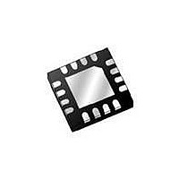
STPMS1BPQR STMicroelectronics, STPMS1BPQR Datasheet - Page 16

STPMS1BPQR
Manufacturer Part Number
STPMS1BPQR
Description
IC SMART SENSOR ASSP W/PGA 16QFN
Manufacturer
STMicroelectronics
Type
Smart Sensorr
Datasheet
1.STPMS1BPQR.pdf
(23 pages)
Specifications of STPMS1BPQR
Input Type
Analog
Output Type
Digital
Interface
Digital
Mounting Type
Surface Mount
Package / Case
16-VQFN
Supply Voltage (max)
5.5 V
Supply Voltage (min)
3.2 V
Product
Dual Channel Smart Sensor
Lead Free Status / RoHS Status
Lead free / RoHS Compliant
Current - Supply
-
Lead Free Status / Rohs Status
Lead free / RoHS Compliant
Other names
497-10475-2
Available stocks
Company
Part Number
Manufacturer
Quantity
Price
Company:
Part Number:
STPMS1BPQR
Manufacturer:
STM
Quantity:
4 809
Theory of operation
Figure 17. Power supply external connection scheme
16/23
The band-gap voltage reference is used as the reference level source for the low-drop
module and for the AD converters. This module produces several bias currents and voltages
for all other analog modules.
The low-drop regulator generates the +3.0 V power supply level. This level is used to power
the DC buffers, pre-amplifier, and AD converter pair in the analog part of the device and
whole digital part. It is brought out as V
there is a power on reset (POR) detection circuit, which blocks all functions of the STPMS1
by asserting the reset condition whenever a V
In order to enable proper operation of the switched capacitor (SC) section of AD converters,
two DC buffers are added to the device. One is buffering the voltage reference level and the
other is buffering the level of value equal to (VDD-VSS)/2.
The AD converter block is further split into a voltage and current channel. Each channel
consists of a differential pre-amplifier, SC integrator, comparator, amplifier bias block, and all
necessary switches. The voltage channel SC integrator has a gain of 2 and there is no pre-
amplifier block. The current channel SC integrator has a gain of 2 or 8, which can be
selected by MS0 input, and has a pre-amplifier with a gain of 4.
The amplitude of the input signal to the AD converter block must be kept less than 0.45 V
The output of each channel is input to the digital module as ΣΔ stream.
For the operation of the analog part, a set of five clock signals is provided from the digital
module. These signals derive from the CLK signal. Two of them are used to run the
conversion, the next one is used as the chopper signal for the voltage channel and the last
two are used as chopper signals for the current channel. All these signals are connected to
the control signal module, which consists of standard digital cells powered from an analog
supply. It produces all the necessary signals and switch controls of the AD converters.
100nF
100nF
100uF
100uF
GND
GND
GND
GND
VDD
VDD
VDD
VDD
Analog Supply
Analog Supply
3.3 -5.0V
3.3 -5.0V
Doc ID 16524 Rev 2
GND
GND
DD
for external connections. As part of low-drop,
CC
supply level is less than +2.5 V.
MS1
MS1
MS0
MS0
VDD
VDD
VDD
VDD
AM07836v1
AM07836v1
100nF
100nF
STPMS1
ref
.


