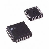
AD698APZ Analog Devices Inc, AD698APZ Datasheet - Page 6

AD698APZ
Manufacturer Part Number
AD698APZ
Description
IC LVDT SIGNAL COND 28-PLCC
Manufacturer
Analog Devices Inc
Type
Signal Conditionerr
Datasheet
1.AD698APZ.pdf
(12 pages)
Specifications of AD698APZ
Input Type
Voltage
Output Type
Voltage
Interface
LVDT
Current - Supply
15mA
Mounting Type
Surface Mount
Package / Case
28-LCC (J-Lead)
Bandwidth
20kHz
Supply Voltage Min
13V
Supply Voltage Max
36V
Digital Ic Case Style
LCC
No. Of Pins
28
Operating Temperature Range
-40°C To +85°C
Msl
MSL 5 - 48 Hours
Supply Voltage Range
13V To 36V
Audio Ic Case Style
PLCC
Base Number
698
Rohs Compliant
Yes
Lead Free Status / RoHS Status
Lead free / RoHS Compliant
Lead Free Status / RoHS Status
Lead free / RoHS Compliant, Lead free / RoHS Compliant
Available stocks
Company
Part Number
Manufacturer
Quantity
Price
Company:
Part Number:
AD698APZ
Manufacturer:
Analog Devices Inc
Quantity:
135
Part Number:
AD698APZ
Manufacturer:
ADI/亚德诺
Quantity:
20 000
AD698
CONNECTING THE AD698
The AD698 can easily be connected for dual or single supply
operation as shown in Figures 7, 8 and 13. The following gen-
eral design procedures demonstrate how external component
values are selected and can be used for any LVDT that meets
AD698 input/output criteria. The connections for the A and B
channels and the A channel comparators will depend on which
transducer is used. In general follow the guidelines below.
Parameters set with external passive components include: exci-
tation frequency and amplitude, AD698 input signal frequency,
and the scale factor (V/inch). Additionally, there are optional
features; offset null adjustment, filtering, and signal integration,
which can be implemented by adding external components.
DESIGN PROCEDURE
DUAL SUPPLY OPERATION
Figure 7 shows the connection method for half-bridge LVDTs.
Figure 8 demonstrates the connections for 3- and 4-wire
LVDTs connected in the series opposed configuration. Both ex-
amples use dual 15 volt power supplies.
A. Determine the Oscillator Frequency
Frequency is often determined by the required BW of the sys-
tem. However, in some systems the frequency is set to match
the LVDT zero phase frequency as recommended by the
manufacturer; in this case skip to Step 4.
1. Determine the mechanical bandwidth required for LVDT
2. Select minimum LVDT excitation frequency approximately
+15V
Figure 7. Interconnection Diagram for Half-Bridge LVDT
and Dual Supply Operation
–15V
position measurement subsystem, f
ample, assume f
10 f
SUBSYSTEM
6.8µF
. Therefore, let excitation frequency = 2.5 kHz.
100nF
SUBSYSTEM
15nF
C2
C1
R1
10
11
12
1
2
3
4
5
6
7
8
9
–V
EXC1
EXC2
LEV2
FREQ1
FREQ2
BFILT1
BFILT2
–BIN
LEV1
+BIN
–AIN
= 250 Hz.
S
6.8µF
AD698
FEEDBACK
OFFSET1
OFFSET2
OUT FILT
–ACOMP
+ACOMP
SIG OUT
SIG REF
AFILT2
AFILT1
SUBSYSTEM
+AIN
+V
S
100nF
19
16
14
13
24
23
22
18
17
15
21
20
R4
R3
. For this ex-
R2
33k
C4
C3
1000pF
REFERENCE
SIGNAL
V
OUT
R
L
–6–
3. Select a suitable LVDT that will operate with an excitation
4. Select excitation frequency determining component C1.
B. Determine the Oscillator Amplitude
Amplitude is set such that the primary signal is in the 1.0 V to
3.5 V rms range and the secondary signal is in the 0.25 V to
3.5 V rms range when the LVDT is at its mechanical full-scale
position. This optimizes linearity and minimizes noise suscepti-
bility. Since the part is ratiometric, the exact value of the excita-
tion is relatively unimportant.
5. Determine optimum LVDT excitation voltage, V
+15V
–15V
Figure 8. AD698 Interconnection Diagram for Series
frequency of 2.5 kHz. The Schaevitz E100, for instance, will
operate over a range of 50 Hz to 10 kHz and is an eligible
candidate for this example.
Opposed LVDT and Dual Supply Operation
4-wire LVDT determine the voltage transformation ratio,
VTR, of the LVDT at its mechanical full scale. VTR =
LVDT sensitivity
LVDT sensitivity is listed in the LVDT manufacturer’s cata-
log and has units of volts output per volts input per inch dis-
placement. The E100 has a sensitivity of 2.4 mV/V/mil. In
the event that LVDT sensitivity is not given by the manufac-
turer, it can be computed. See section on determining LVDT
sensitivity.
R
S
PHASE LAG
A
C
6.8µF
R
T
C
B
D
R
C1 35 F Hz/f
S
100nF
C2
C1
1M
R1
Maximum Stroke Length from null.
A
C
PHASE LEAD
R
C
T
10
11
12
1
2
3
4
5
6
7
8
9
B
D
–V
EXC1
EXC2
FREQ1
FREQ2
BFILT1
BFILT2
–BIN
LEV1
LEV2
+BIN
–AIN
S
R
C
S
6.8µF
AD698
EXCITATION
FEEDBACK
OFFSET1
OFFSET2
OUT FILT
–ACOMP
+ACOMP
SIG OUT
SIG REF
PHASE LAG = Arc Tan (Hz RC);
PHASE LEAD = Arc Tan 1/(Hz RC)
WHERE R = R
AFILT2
AFILT1
+AIN
+V
S
100nF
19
16
24
23
22
20
18
17
15
14
13
21
R4
R3
S
// (R
R2
C4
C3
S
NETWORK
C
A
LAG/LEAD
EXC
+ R
PHASE
1000pF
REFERENCE
T
)
. For a
SIGNAL
REV. B
B
D
V
OUT
R
L


